Use the new Sheet corner  function to create a riveted corner, reinforced with a stiffener, between 2 sheet flanges. The flanges can have different lengths and different bend angles. You can apply this connection type to milling edge zones and cylindrical bend zones.
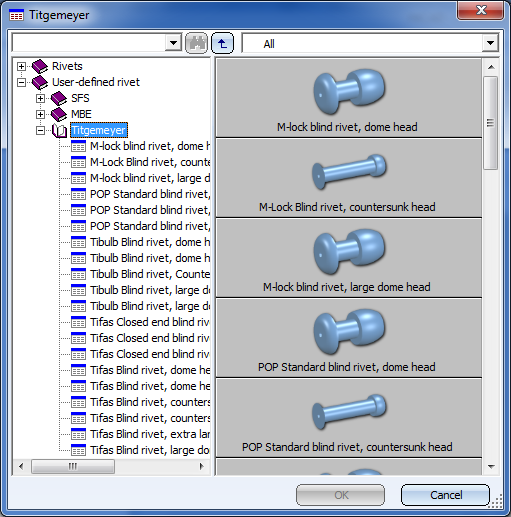
When you call the function the following dialogue window will be displayed:
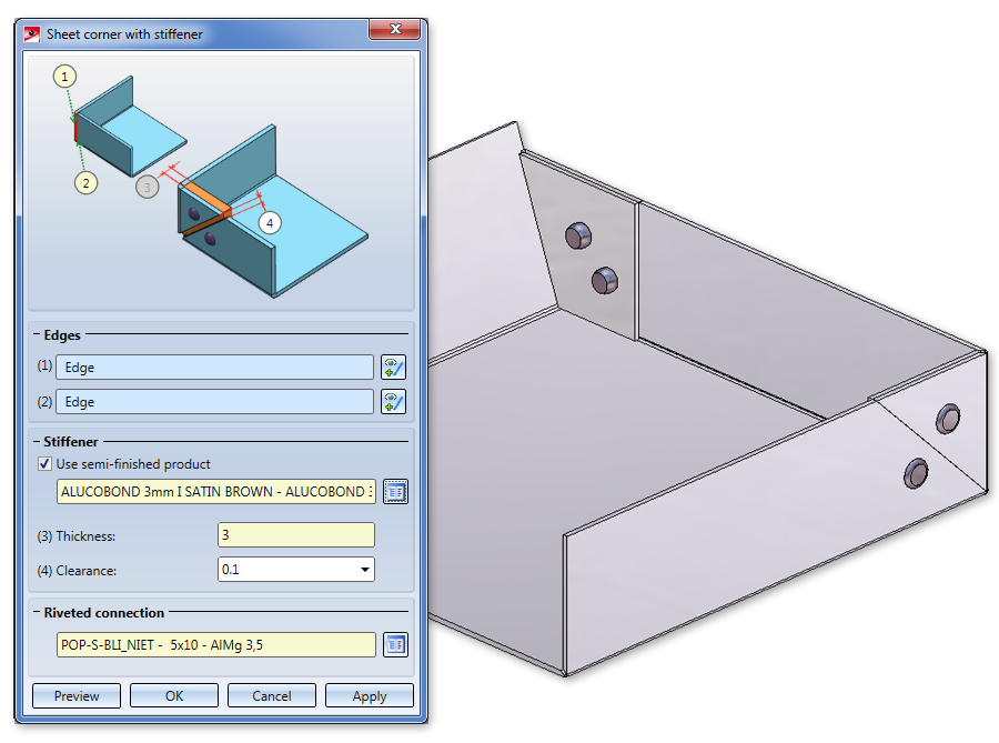
You determine the position of the connection by identifying two flanges on the longitudinal edge of the front side. If you want to identify a different flange, click the icon beneath Edges and then identify the desired edge.
The connection will be applied to the last identified flange. If the flanges have different lengths, these will remain unchanged.
If you select a semi-finished product here, the Thickness (3) of the sheet will be automatically entered here. The standard for semi-finished products can be taken from the Catalogue Editor with a click on the  icon. With a double-click on the Sheet corner feature you can activate or deactivate the semi-finished product later.
Select the riveted connection from the catalogue. You can choose between SFS and Titgemeyer.
If you have entered all required data you can create the connection. Click Preview to check and, if required, modify the connection. If you click Apply, the sheet corner will be created, and the dialogue window remains open, allowing you to apply the data to other sheet corners. If you click OK, the sheet corner will be created, and the window will be closed. Clicking Cancel closes the dialogue window and discards the data without creating the sheet corner.
The DXF export function for developments has been revised completely. You can choose between the following 3 options:
When exporting a development as DXF file (Sheet Metal > Sheet development) you have the option
When you have identified an edge of the development, the standard dialogue window for the saving of a file will be opened. On the right hand side you can choose the export settings - either Only section contour or Complete development.
For the DXF export you need the file HCADACAD.DAT. It contains, for instance, the assignment of the HiCAD elements for specific AUTOCAD layers. This file can be customized and is located in the HiCAD subdirectory SYS. Do not save the file with the file name extension .DAT, but with .DA1, .DA2 or .DA3 after its customisation. In this context, please also read this information.
The Develop sheets and export as DXF  (Sheet Metal > Sheet development
  > Extras) function exports the section contour or the complete development of Steel Engineering plates. in the process, one temporarily generated development will be output for the export. You can choose between various sheet development parameters.
For the selection of the sheet development parameters the following options are available:
|
From drawing |
Use this option to load the parameters of the default settings for the drawing. The default setting for new drawings can be specified at Sheet Metal > Sheet development > Default setting. |
|
Manual settings |
Clicking the |
|
Favourite |
The Favourites |
|
According to filter list from configuration |
Use this option to load the assignment of the development favourites to the part filters (Sheet Metal sheets or Steel Engineering plates) from the Configuration Editor (at Sheet Metal > Sheet development > Filter-Development parameter assignment. Part filters are filters that have been predefined by the ISD and also the manual filters for part search that have been stored as Favourites. |
The orientation is only unambiguous if it has been determined with the Processing direction function beforehand.
The file name can be configured in the Annotation Editor with a click on the  icon. To do this, apply, for instance, the part attribute "Item number" from the Sheet Metal part. If the part attributes set in the Editor cannot be applied to the sheets, you have the option to enter your own file name.
For the DXF export you need the file HCADACAD.DAT. It contains, for instance, the assignment of the HiCAD elements for specific AUTOCAD layers. This file can be customized and then saved with the file name extension .DA1, .DA2 or .DA3.
The selection of sheets can either take place in the drawing  or by adding of all sheets
  .
.
When you click on the Export button, temporary developments will be generated and output of all sheets in the export list, according to the specified parameters. The status icon  will indicate problems that may occur. The files will then be located in the specified directory.
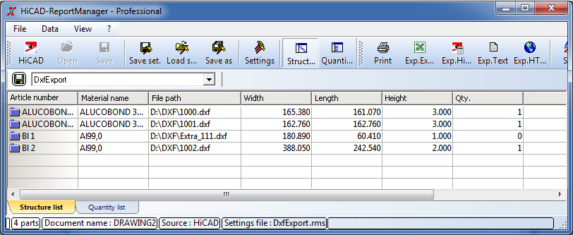
The Close & Report button activates the Report Manager and creates a BOM. If you did not itemize the Sheet Metal part in HiCAD, quantities will be set on 0 here.
When exporting multiple sheet developments as DXF files (Sheet Metal > Sheet development > Extras) you have the option
Use this function to export several developments with different parameter settings of one Sheet Metal part as DXF, e.g. LVD and Bystronic.
The file name can be configured in the Annotation Editor with a click on the icon. To do this, apply, for instance, the part attribute "Item number" from the Sheet Metal part. If the part attributes set in the Editor cannot be applied to the sheets, you have the option to enter your own file name.
For the DXF export you need the file HCADACAD.DAT. It contains, for instance, the assignment of the HiCAD elements for specific AUTOCAD layers. This file can be customized and then saved with the file name extension .DA1, .DA2 or .DA3.
The selection of developments can either take place in the drawing or by adding of all developments .
When you click on the Export button, all developments in the export list will be output as DXF files, according to the specified parameters.
The Close & Report button activates the Report Manager and creates a BOM. If you did not itemize the Sheet Metal part of the development in HiCAD, quantities will be set on 0 here
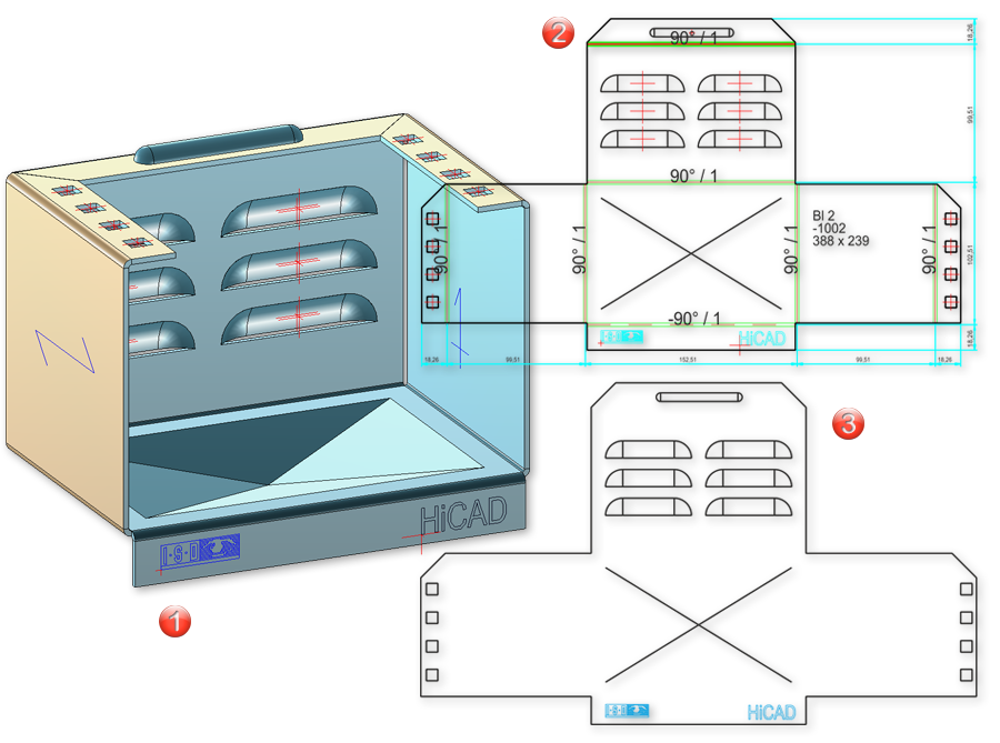
(1) Sheet Metal part
(2) DXF of the entire development
(3) Section contour
For DXF export you will need the file HCADACAD.DAT. This file contains:
The file can be customized and is located in the HiCAD SYS directory. After customization, do not save the file with the extension .DAT, but with .DA1, .DA2 or .DA3.
For the export of developments to COBUS NCAD use the file HCADACAD_COBUS.DAT in the HiCAD SYS directory. If you want to use this file, save it with the matching file extension (e.g. HCADACAD.DA1).Click here for more information.
To export a CSV file in the Report Manager, call the Settings function and go to the Export - Text tab. Activate the option Query file name before saving and deactivate Transfer header information. Enter a comma or a semicolon for Separator for column. Confirm with OK. Then, call the Exp.Text
  function and choose the file type *.CSV.
When processing a coated Sheet Metal part, the coating will not be automatically applied to the respective processing (e.g. to new flanges, bores or corner processings). You can now use the new Extend coating  function to apply the coating to the new or processed elements. To change the coating colour, simply call the Coating feature.
(1) Front surface of bore (front surface like outer side)
(2) Front surface of flange, bend zone (front surface like outer side)
(3) Outer side of flange
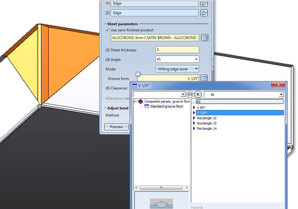
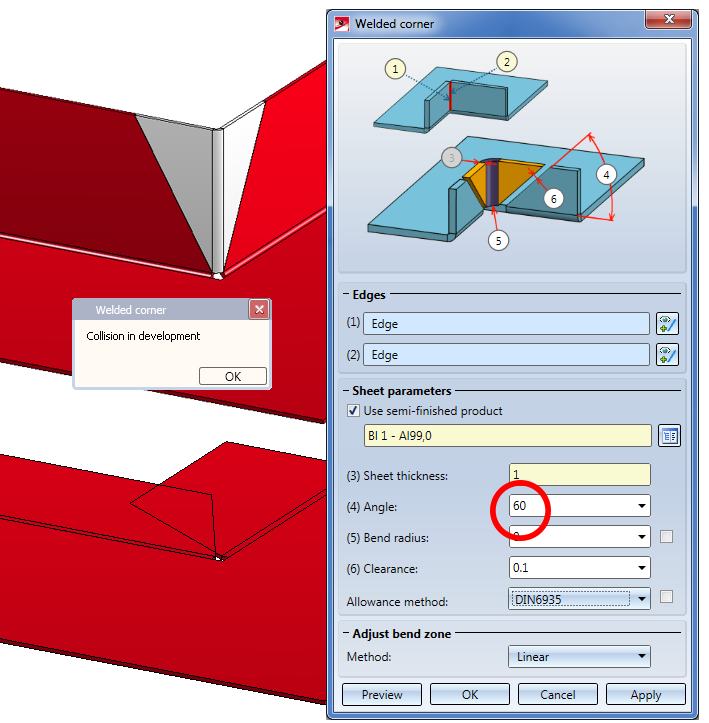
Composite panels such as ALUCOBOND are deformed by means of milling edges. Therefore, the new parameters Mode and Milling form have been added to the Welded corner dialogue window.
In the Mode filed you can choose between Bend zone, Milling edge zone and Milling edge zone, inverted options. For the milling edges you can then select, in the Groove form field, the matching milling tool from the catalogue Factory standards > Composite panels, groove form.
The system attributes
|
§L2D |
Development length |
|
§B2D |
Development width |
|
§T2D |
Sheet thickness |
will be considered for the transfer of the part attributes to the Report Manager. This does however not apply to database BOMs.
The placing of textures on the individual sub-parts of a Sheet Metal part has been changed in such a way that the appearance of the assigned texture will be consistent - both with regard to the alignment of the texture and the transitions between neighbouring sub-parts:
Texture on composite panels
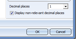
For attribute values that are output with decimal places, e.g. for sheet developments, you have now the option to determine the number of decimal places at the bottom right of the dialogue. You can specify whether non-relevant decimal places (e.g. final zeroes) are also to be displayed by activating or deactivating the checkbox.
New dimensioning rules for sheets and plates are now available:
155 SHEETMETAL_FLANGE_INSECT / 156 SHEETMETAL_BENDINGANGLE_INSECT
Rule 155 dimensions the flange length of sheets in sectional views, Rule 156 dimensions the bend angle of sheets in sectional views. In case of diagonal angles the theoretical intersection point between 2 flanges will be dimensioned.
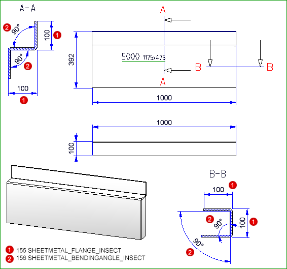
The recommended settings can be found here. At the same time, these settings are the new default settings for the sectional views of sheets in Workshop drawings (Usage: DEFAULT(KANTBLECHE).
As of HiCAD 2018 SP2, the section for the generation of sectional views for derived drawings will always be made at the shortest bend zone. The sectional views will be generated with limited depth and placed perpendicular to each bend zone.
The Settings for sectional views of sheets dialogue window has also been modified.
The following settings are now possible here:
The previously available setting options "Angular dimension in sections" and "Offset go-side" are no longer available.
The representation of angular dimensions can be determined via the new dimensioning rule 156, and the distance of the go-side via the settings in the Configuration Editor at Drawing > Annotations > Coating line in sectional view.
When deriving drawings you have now the option to specify for sectional views of Sheet Metal parts whether 90° bend angles are to be dimensioned or not. According to the default setting, all bend angles will be dimensioned.
To switch off the dimensioning of 90° bend angles, you need to manually adjust the system files
STAB3DPAR.DAT
Change the setting for the line below as follows:
Rechte Winkel darstellen für Öffnungswinkel von Biegezonen von Kantblechen? 1:ja, 0:nein
0
STW_DIMSETTINGS.XML
Change the setting for the line below as follows:
</PARAM><PARAM Name="SHOWRIGHTANGLEOFBENDZONE" Typ="INT" Value="0">
If this line does not exist, add it manually.
You can now also use the functions of theCorner/Mitre menu to process different Sheet Metal main parts. The functions
 and
and 
have therefore be removed.
In the Through point  mode you can switch the start point of the cut plane from the inner side to the outer side. This means that the first point of the cut plane is located in the theoretical lengthening of the inner or outer edges of the flanges. Also, all point options are available to you.
Mitre cut between different sheets
First intersection point through outer edge, changed via right-click
dialogue window for the sheet development parameters you can find the new Processings checkbox beneath Dimensioning. Activate this checkbox if you want bores and subractions to be dimensioned.
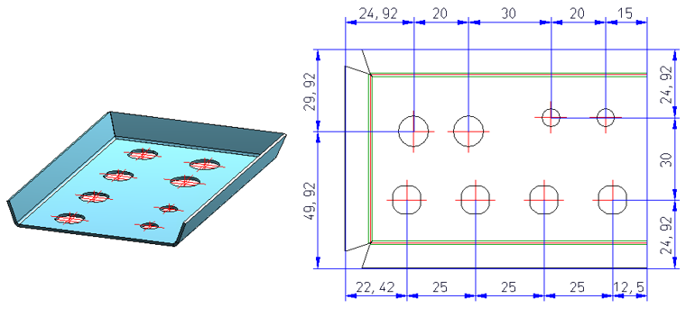
Dimensionings for processings
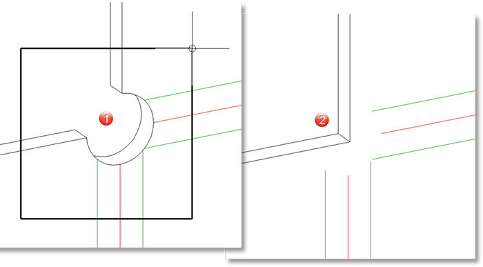
The Adjust milling tool paths for production option refers to sheet corners where three milling edge zones converge. In the development, the lines do normally not converge in a common intersection point.
Therefore you have now the option to adjust the milling lines in such a way that they end in one common point.
It is important that only the milling lines are adjusted, and not the 3-D geometry.
If there are two converging milling lines, the milling lines will be lengthened / shortened, so that they converge in a common intersection point.
The parameters (Colour, Line type, Layer) of the powder marking lines can be specified via Sheet development > Update > Default setting  and, in the dialogue window, Extended settings
  . The settings apply only to the 3-D sheet development.
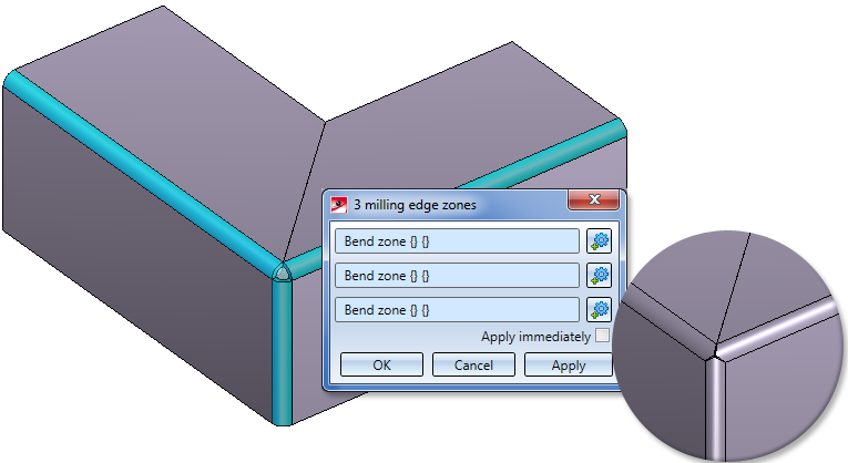
Use this new 3 Milling edge zones  function to close a corner in your Sheet Metal construction with 3 milling edge zones. Just identify the milling edge zones and confirm the processing with OK.
Use this the Text position on development  function to determine the position and direction of auxiliary texts on a sheet development. To evaluate the text position, you need to activate the Auxiliary text checkbox in the dialogue window for the sheet development parameters and choose the setting Positioning: Inside. If you select "Inside" but set no positioning symbol, the annotation will be placed as usual, i.e. HiCAD will search for a free space on the development.
In the catalogue you find the text position symbol  in various sizes in the Text alignment symbol table at Factory standards > Symbols > Text alignment. If desired, you cann add your own sizes to this table.
The text position symbol is visible on the 3-D sheet, but invisible on the development on Layer 0.
The text position symbol is also considered for identical part search and referencing: Two sheets with different text position symbols are considered as "unequal".
The Attach flange function now has two new reference and fitting modes. The Reference drop down list now offers the option to attach the flange angle-dependent to the inside or outside. The Fitting mode drop-down list offers the same options for connecting flanges.
The Article number is editable, even if the created sheet is generated from a semi-finished product from the catalogue. The catalogue column BZ is not necessarily linked to the article number in the part attributes; BZ can be linked to any part attribute (e.g. $01 Designation 1).
The Sheet from solid function now also copies the article number of the original part.
You have now the option to insert hole patterns on developed sheets, i.e. after a bending simulation. In the process, the hole pattern (like bores) can be applied across multiple flanges and bend zones.
You can access this function at 3-D Standard > Standard processings > Bore > Hole pattern.
The Delete coating line function for sectional views of sheets has been replaced with the new Hide/show coating lines  function. You access the function by right-clicking the coating line in the sectional view and choosing the function in the context menu.
Coating lines can be hidden or shown in the active view or in all sectional views. One distinguishes between coating lines on the inner side and the outer side.
If all coating lines have been hidden, the lines can be redisplayed again via the context menu for sheets: In the sectional view, right-click the sheet and choose Properties > Coating line.
TheShow/hide edgesfunction (at Views > Properties) has been enhanced (new Processing planes checkbox) and renamed to Hide/show elements in view.
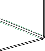
Composite panels, e.g. ALUCOBOND panels, can be deformed by means of milling and folding techniques. The resulting bend zone geometrically differ from the cylindrical bend zones. Therefore, HiCAD also offers the option to choose (besides bend zones) milling edge zones.
When choosing the Attach flange function, you can now choose between bend zone and milling edge modes.
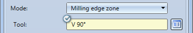
The following options are available:
|
|
Bend zone The bend zone has the specified bend radius. |
|
|
|
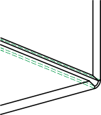
Milling edge zone Bend zone with chosen tool (milled inside). |
|
|
|
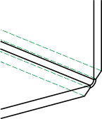
Milling edge zone, inverted Bend zone with chosen tool (milled outside). |
|
For milling edge zones you have the option to click the Via catalogue button next to Tool and choose the desired milling tool from the Composite panels, groove form catalogue.
The milling tool path will be displayed if you have activated Bend zone checkbox beneath Representation in the Sheet development default settings dialogue. The appearance of the tool path is determined on the Milling + Folding tab of the Extended settings dialogue window that you open with a click on the symbol.
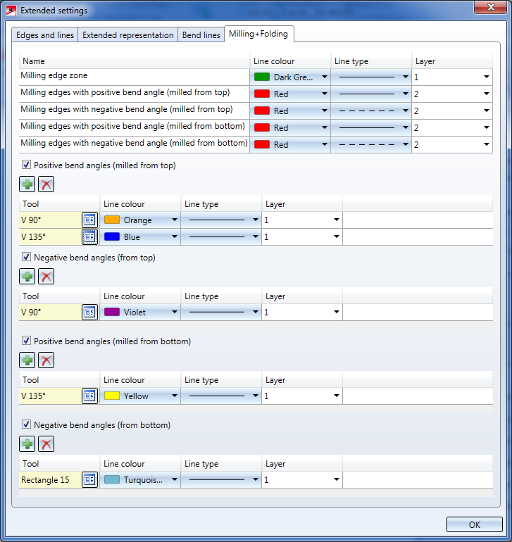
In the upper part of the dialogue you can specify the settings for Line colour, Line type and Layer of the different tool paths.
You can then specify tool-dependent line parameters for positive and negative bend angles; "milled from top" refers to the edge that you chose for Sheet alignment: Automatic (see above).
By the specification of tool-dependent settings the milling tool paths in the upper part of the dialogue may be overwritten.
The  icon adds a row for a tool from the catalogue. Click the
  icon to delete a marked row again.
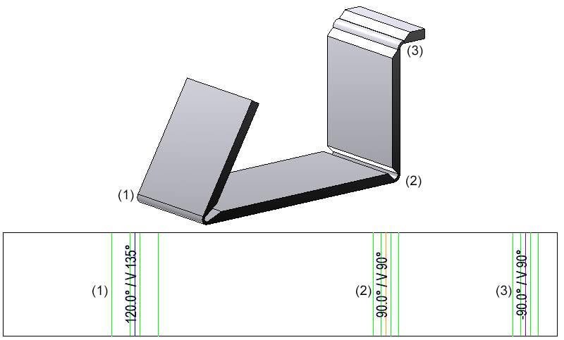
(1) Positive bend angle, milled from top, Tool V 135°
(2) Positive bend angle, milled from top, Tool V 90°
(3) Negative bend angle, milled from top, Tool V 90°
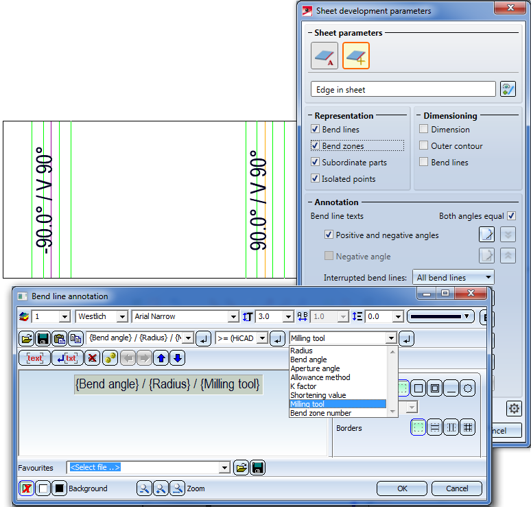
The bend line text was expanded by the Milling tool attribute by clicking the icon next to the corresponding option.
The Sheet along sketch now allows you to insert milling edge zones and/or bend zones. The pre-settings for the complete Sheet Metal part are entered in the Sheet parameters area. In the Bend zones area or (later) via the Feature, you can specify a tool from the catalogue for each milling edge zone, as well as an individual setting for the milled side.
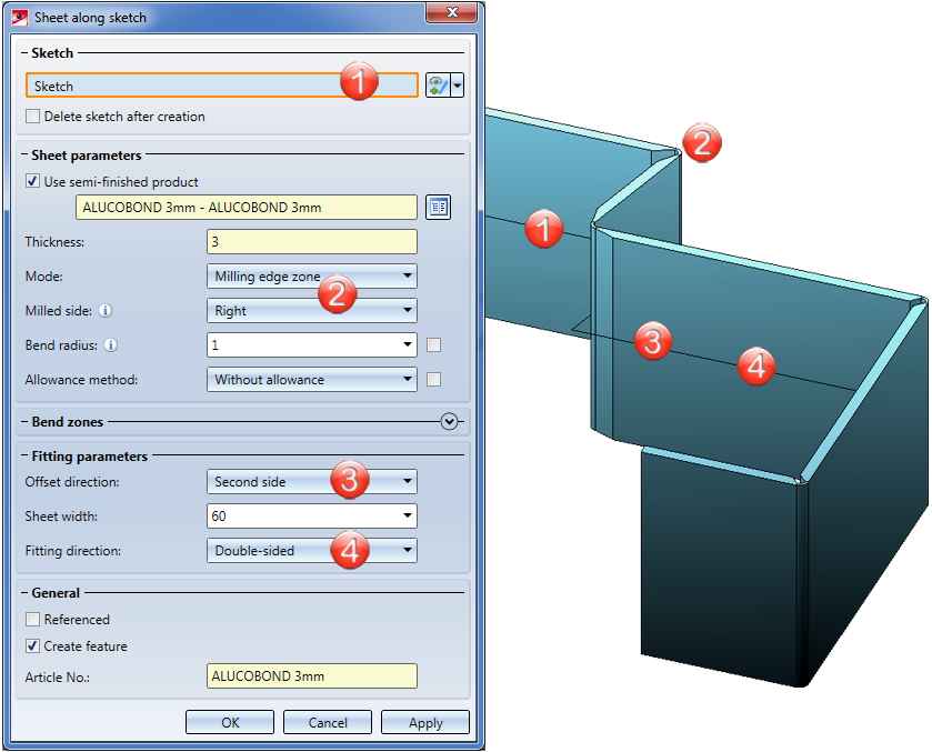
The output of the milling tool can be selected in the Annotation Editor via the attributes. The tool that was chosen for milling edge zone creation will be output at the bend line.
New in the catalogue are milling tools for processing of composite panels. These can be found at Factory standards > Composite panels, groove form.
The Adjust bend zone  function also adjusts the new milling edge zones.
The "Process corner" and "Mitre" function groups have been combined into one function group called Corner/Mitre.
|
Corner/Mitre |
|
|---|---|
|
|
|
|
Pull-down menu |
|
|
|
|
|
|
|
|
|
Corner processing/Mitre, betw. Sheets (moved to the Corner/Mitre menu as of SP1) |
|
Pull-down menu |
|
|
|
Corner processing/Mitre, Individual - betw. Sheets (moved to the Corner/Mitre menu as of SP1) |
When you choose Sheet Metal > Corner/Mitre > Sheet  a revised dialogue window containing various functions for mitre cuts and corner processings will be displayed:
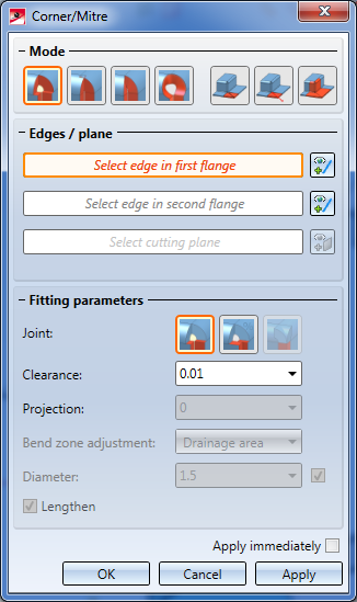
Proceed as follows:
Depending on the selected mode, some further options in the dialogue may be greyed out.
If you want to identify a different edge, click the  icon beneath Edges/plane to identify the edge.
As soon as you have entered all required data, a preview will be displayed.
If you click Apply, the processing will be applied while the dialogue window remains open, enabling you to make further adjustments if required. If you click OK, the processing will also be applied, but the window will be closed.
|
Corner/Mitre dialogue window - Possible options |
|
|---|---|
|
|
Mode: Close corner, free bend zone |
|
Fitting parameter Joint |
|
|
|
|
|
|
|
|
|
|
|
|
Mode: Close corner, closed bend zone |
|
Fitting parameter Joint |
|
|
|
|
|
|
|
|
|
|
|
|
|
|
|
|
|
|
|
|
|
Mode: Close corner, round |
|
|
|
|
|
Mode: Mitre |
|
|
|
|
|
Mode: Mitre, Through point |
|
|
|
|
|
Mode: Mitre, with neighbours |
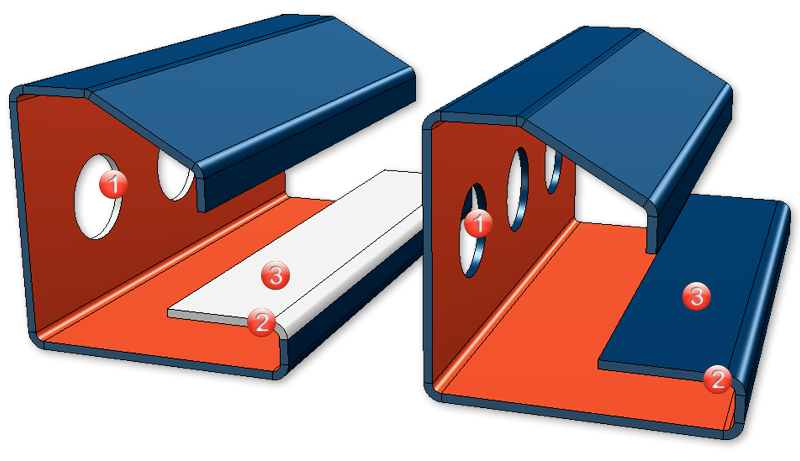
On the Change length function group of the Sheet Metal tab you find the Trim  function. When you call the function, a new, revised dialogue window that offers different trimming options will be displayed:
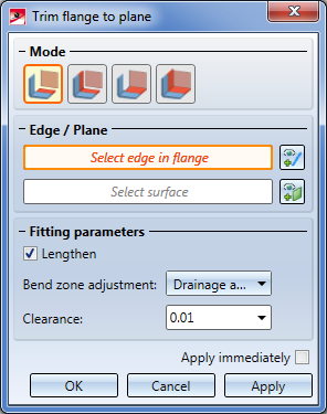
Proceed as follows:
Depending on the selected mode, some options may be greyed out.
If you want to identify a different flange, click on the icon beneath Edge / Plane and identify the desired edge.
Here, too, you can select a different plane by clicking on the  icon.
icon.
 checkbox if there are flanges that do not reach up to the cut plane.
 If you click Apply, the change will also be inserted, but the window will remain open, allowing you to trim further sheets. If you select Cancel, the window will be closed, and no change will be applied. If you have activated the Apply immediately checkbox, the entered data will be applied instantly.
Subsequent changes can be made via the Feature log: Double-click on the Trim to surface feature and change the data in the displayed dialogue window.
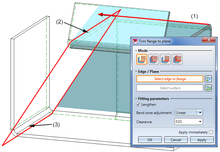
(1) Edge of the sheets to be trimmed
(2) First edge of cut plane
(3) Second edge of cut plane
It is now possible to distinguish between the lines of outer and inner contours in developments. Inner contours are all contours that can be cut out of the sheet and are no standard processings.
This allows you, for instance, to define the adjustment of the layers for the DXF export more accurately.
Colour, type and layer can be specified in the Extended settings of the development parameters.
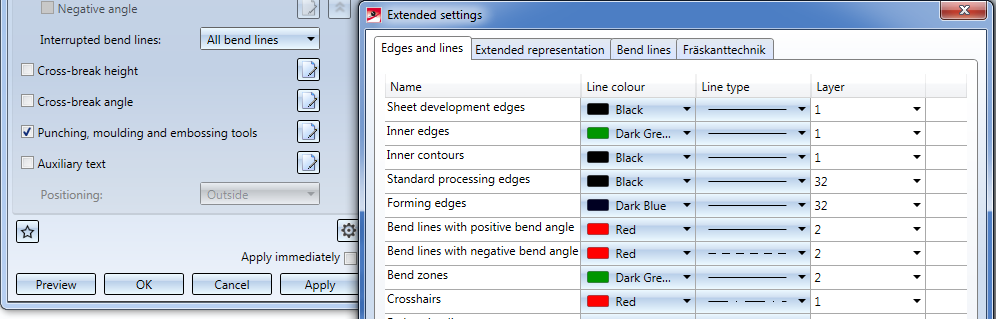
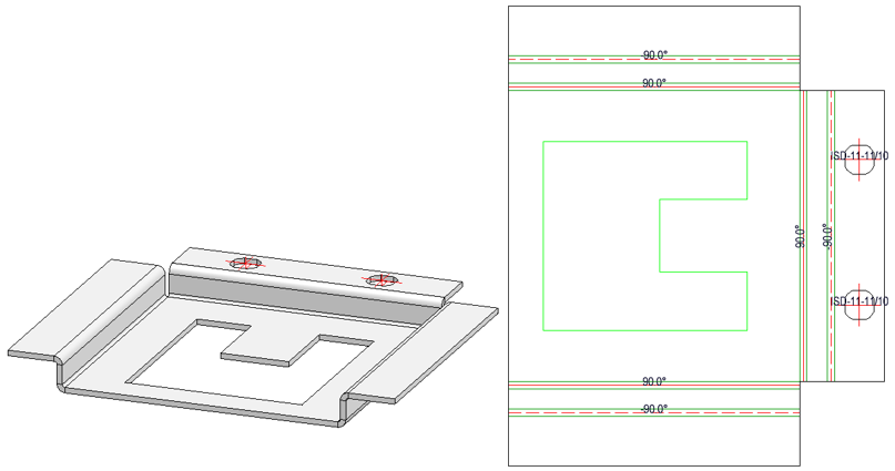
Inner contours have the line colour Green.
The analytical development with the functions
now offers the option to develop facets lying on a torus.
This takes place approximatively by means of a double development, first with regard to the torus axes and then, once more, with regard to the cylinder axis resulting from this development.
Therefore, the following warning message will be displayed:
The development contains a torus that might not have been developed correctly. Please check the result!
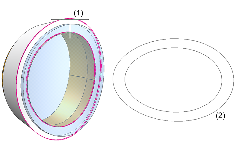
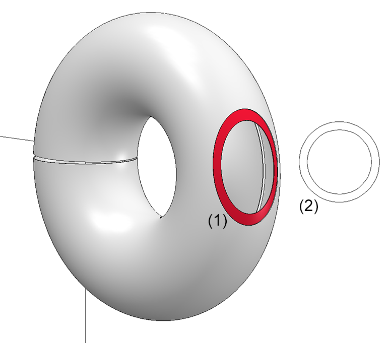
(1) Facet
(2) Development
In the Create sheet development dialogue window you can specify in the Sheet alignment: Automatic mode the criteria according to which the upper sheet part is to be determined for development creation. For instance, you can generate the development in such a way that the coated side will be the upper side.
When milling composite panels the coated side is normally located at the bottom. With the Invert upper side option you can flip the upper side to the bottom.
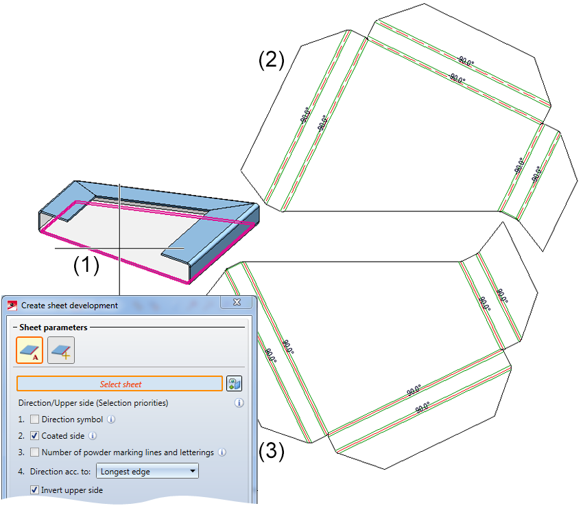
(1) Sheet Metal part
(2) Development of coated side
(3) Development of coated side, inverted
In sheet developments you can now define whether isolated points of the Sheet Metal part are to be hidden or shown. The position of the points (in the development) refer to the flange or the bend zone that was active during creation. If the main part is active, no points will be developed.
The setting affects only the Isolated 3-D points  supplied by the Sheet Metal part. Isolated points in the development that have been created subsequently are always visible.
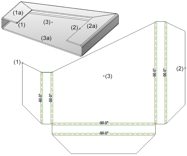
(1) Isolated point, (1a), active sheet flange
(2) Isolated point, (2a), active sheet flange
(3) Isolated point (3a), base sheet active
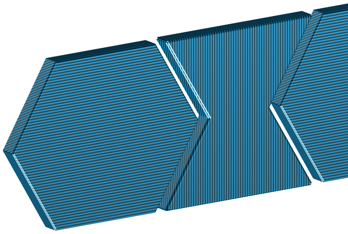
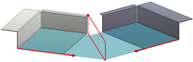
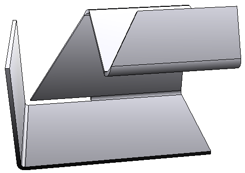
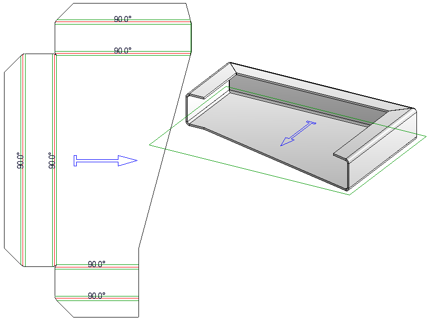
If two flanges touch one another (without clearance) during development, a line representing a "separation cut" will be inserted into the development (see image below). If the front face of a bend zone directly touches a flange, such a separating line will be inserted here, too.
Through the merging of flanges and bend zones during a sheet development, edges that belong to the outer contour and that will be needed for blank creation can be lost. Therefore, those separating lines will be inserted, as free edges, at their position in the development.
The separating lines are inserted at positions where contour edges are identical before the merging, and where at least one of these identical edges originates from a flange.
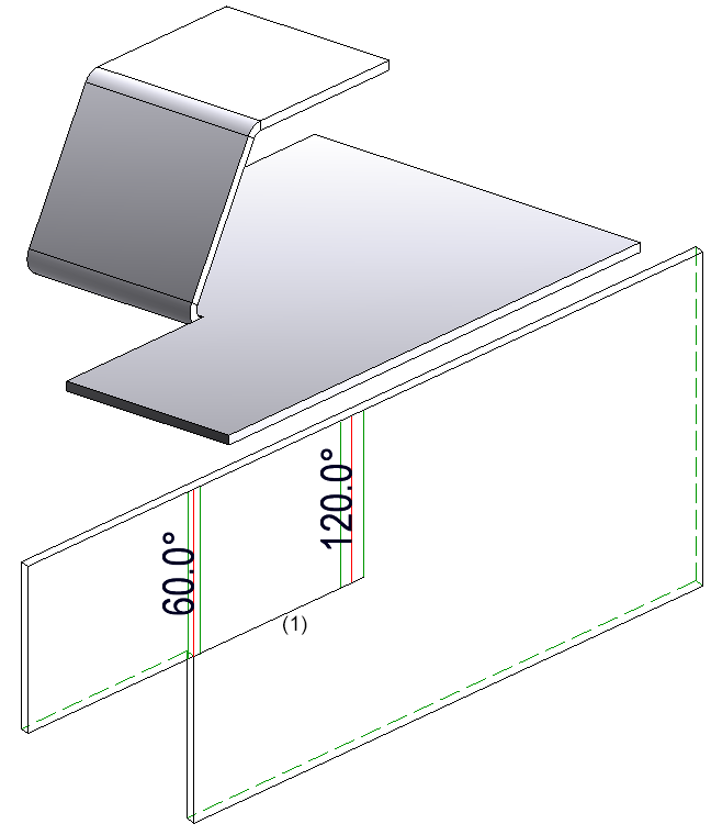
(1) Separating line
You can use the Acute corner function to simplify developments.
The corners will then be simplified. You can then process further corners of the development or end the function by pressing the middle mouse button.
Processings of developments by the functions
that are offered to you when you right-click a sheet development and choose Process development will now be retained even after a Feature recalculations and development updates.
The Direction arrows table (atWerksnormen/Symnbole/Pfeile) now contains the new symbols Direction symbol Composite panel and Direction symbol, one-sided. With these symbols the direction of coatings or textures can be determined. When creating sheet developments the direction can be optionally used for the alignment of the development.
The following Direction arrows can now be inserted:

 and
and  .
.
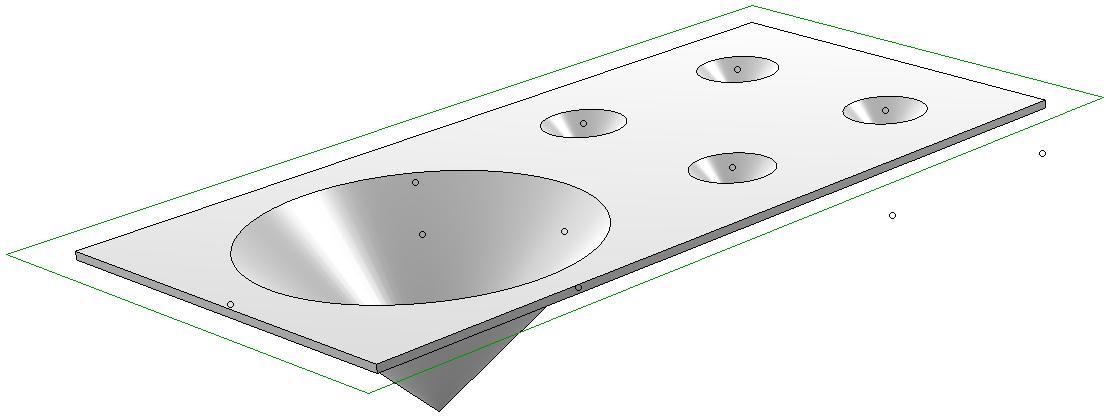
The new Hole pattern function allows you to insert regular patterns of defined holes into parts or sheets.
Possible hole types are round holes, square holes, slots and special holes that can be defined with the help of sketches. The holes can be arranged in straight, staggered, diagonally staggered or freely staggered rows according to DIN.
You can add your own moulding tools to the library. For this you need at least 2 elements: One sketch used by HiCAD to create a material subtraction in the sheet to be processed, and a part containing the actual processing.
When applying the moulding tool, HiCAD initially uses the sketch to create a subtraction in the sheet; then, the part will be positioned and added to the sheet.
Both parts can be parameterized. The thickness of the sheet to be processed will be used as parameter d; other parameters for the size of the processing can be stored in the catalogue in order to be able to apply a moulding tool with many different sizes (see Example).
The welded corner will also be inserted in cases where the affected flanges of the original sheet overlap in developed state. In such cases an error message will now be issued.
The Bending simulation  function can now be found in the Process function group of the Sheet Metal tab.
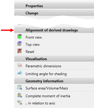
The definition of the front view or top view for assemblies, general 3-D parts, beams and profiles, sheets and plates for derived drawings has been made easier.
For this purpose, the functions at Properties > Alignment of derived drawings in the context menu for part have been changed. Instead of the active view you can now choose any plane for the definition of the front view or top view. The same functions that you would use for the definition of processing planes are available to you.
When selecting certain functions, a shaded polyhedron model preview will be attached to the cursor. For instance, this is the case when inserting or transforming parts, inserting new parts in the preview mode, or inserting standard parts.
This preview can be hidden temporarily by pressing and holding down the SHIFT key. This may be useful when working with complex models due to performance reasons. When the key is released, the preview is visible again.
This behaviour can also be inverted by a corresponding setting in the Configuration Editor at System settings > Visualisation > Temporary preview for part placement Possible setting options are:
The dialogue window for sectional views has been expanded. For Sheet Metal parts you have now the option to specify whether the coating in the sectional view is to be shown or not, by activating or deactivating the Display checkbox beneath Coating in the dialogue window. The coating is displayed in the form of an offset edge, the so-called "coating line". The settings for the representation of the coating line can be found in the Configuration Editor at Drawing > Annotations > Coating line in sectional view.

HiCAD Sheet Metal • General Notes on Sheet Metal Processing • Overview of Functions (3-D SM)
|
© Copyright 1994-2018, ISD Software und Systeme GmbH |
 saved for the development parameters, e.g. LVD, Bytronic or COBUS are offered for selection here.