Powder Marking Lines (3-D SM)
3-D Standard > Standard Processings > Bore  > Powder marking lines
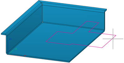
Use this function to manually or automatically project so-called powder marking lines onto the outer surfaces of the active/selected part. Powder marking lines are caused by the outer surfaces of parts lying within the outer surface of the active/selected part (taking certain tolerance values into account). In this way you can, for example, highlight the contours of parts which are to be welded together.
- First, activate the sheet on which the powder marking lines are to be shown. If desired, you can also apply the powder marking lines to part lists (multiple selection) in one step. If does not matter whether these part lists contain individual parts or assemblies.
- Then, select the function and specify via various tolerance values which surfaces and edges are to be considered for powder marking line search.
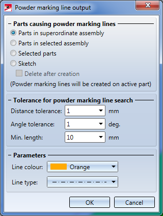
Distance tolerance: Considers only surfaces whose distance to the (parallel) outer surface of the active/selected part is smaller than the specified value.
Angle tolerance: Considers only surfaces whose angle to the (parallel) outer surface of the active/selected part is smaller than the specified value.
Min. length: Edges which are shorter than the specified minimum length will not be considered for powder marking line search.
- Select the colour and the line type for powder marking line representation.
- Select the identification mode for the part and close the input mask with OK. Possible options are:
- Parts in superordinate assembly: The powder marking line search will be performed automatically for the active assembly (or the active main part, respectively). No further identification will be required after closing the dialogue window.
- Part in selected assembly: The powder marking line search will be performed for all outer surfaces of an assembly. After closing the dialogue window, you will be prompted to identify the desired assembly in the ICN.
- Selected part: Applies to the active part. After closing the dialogue window, HiCAD will prompt you to identify the parts causing the powder marking lines.
- Sketch: Activate this option if you want to transfer the lines of a sketch as powder marking lines onto the part. The lines of the sketch must be located on the surface of the part and may be shortened, i.e. excess length of lines will not be taken over as powder marking lines. If the Delete after creation checkbox has been activated, the sketch will be deleted automatically after the powder marking line creation. Please note that sketch elements which are defined as auxiliary geometries will not be taken over as powder marking lines.
- Activate the Sheet Metal parts (or sketches) to be projected.
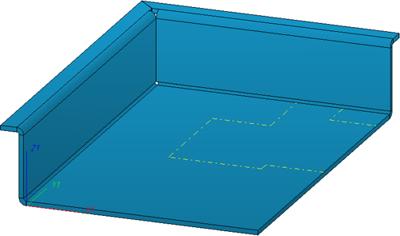
The powder marking lines will be detected and displayed on the assembly main part. Update the 3-D sheet development to apply the powder marking lines.
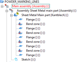
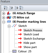
For each powder marking line search, a feature called Powder marking lines will be created for the feature log of the part onto which the lines have been projected. If you have selected the Part with attached part mode, such an entry will be created for each identified attached part (provided that any powder marking lines exist).
If no powder marking lines could be found, the message No powder marking lines created. will be displayed.
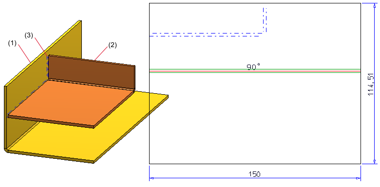
(1) Active main part
(2) Selected main part
(3) Powder marking lines
 Please note:
- When you select an assembly, all its sub-parts will be processed as well.
- Bolting sets will be ignored. The individual elements of a bolting can, however, be selected as parts causing powder marking lines in the Selected parts mode.
- Powder marking lines will be taken over into developments of sheet parts (blanks) and into analytical developments of general 3-D parts. The parameters (Colour, Line type, Layer) of the powder marking lines can be specified via Sheet development > Update > Default setting
 and, in the dialogue window, Extended settings
  . The settings apply only to the 3-D sheet development.
- Powder marking lines are also considered for DXF export.
- The DSTV-NC powder marking line generation functionality is also supported by HiCAD.


Sheet Processing Functions
|
© Copyright 1994-2018, ISD Software und Systeme GmbH
Version 2302 - HiCAD Sheet Metal
Date: 14/09/2018
|
> Feedback on this topic
|