Sheet Metal > Sheet development > Develop sheet
The Develop sheet pull-down menu in the Sheet development function group provides various functions for developing of Sheet Metal parts or 3-D parts, resulting in a 2-D or 3-D development.
You can derive several developments with different parameter settings from one Sheet Metal part. The parameter settings will be saved in the development. The functions for the definition of the development parameters can be found at Sheet Metal > Sheet development > Update  > ....
| Functions | Description | |
|---|---|---|
|
|
This function creates the 3-D development of a Sheet Metal part. The sheet alignment can be determined automatically or via edge selection. If you choose the automatic development, the side with the processing direction symbol will be developed. If the sheet has no processing direction, the coated side will be developed. Then, the upper side will be determined by the number of powder marking lines and letterings. |
|
| Pull-down menu Dev. |
||
|
|
You use this function to develop the lateral surface of a 3-D part, taking into account the connecting angle In other words, all surfaces that do not exceed the connecting angle are taken into account.
The sheet thickness will be queried in case of a possible length change, which makes sense for cylindrical surfaces. For all other surface types the query can be skipped with a right-click (RMB = No length change).
(1) First edge
|
|
|
|
You use this function to develop the lateral surface of a 3-D part and its sub-parts, taking into account the connecting angle. In other words, all surfaces that do not exceed the connecting angle are taken into account. The sub-part must be added to the main part below the connecting angle.
The sheet thickness will be queried in case of a possible length change, which makes sense for cylindrical surfaces. For all other surface types the query can be skipped with a right-click (RMB = No length change).
|
|
|
|
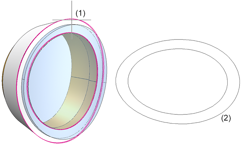
Use this function to develop the outer shell of a 3-D part (e.g. a truncated cone) analytically. You are always prompted to specify an offset (sheet thickness) for the cutting depth. For filleted surfaces, this will cause changes of the surface area of the developed object.
For freeform surfaces: 0.
The tear-open point determines the cutting line in the lateral surface.
You change the parameters of the tear-open edge in the system file ABWCOL.DAT. If you remove the "minus" preceding the parameters, the Layer, the Colour and the Line type will be evaluated. Kanteneigenschaften für Aufreißkanten beim analytischen Abwickeln; Schicht(0-999), Farbe(0-9), Stärke(0-9), Art(0-9); < 0:Kanteneigenschaften von Aufreißkanten werden nicht gesetzt [Edge properties for tear-open edges during analytical development; Layer(0-999), Colour(0-9), Weight(0-9), Type(0-9); < 0:Edge properties of tear-open edges not set] 1711
In this example the tear-open edge is green
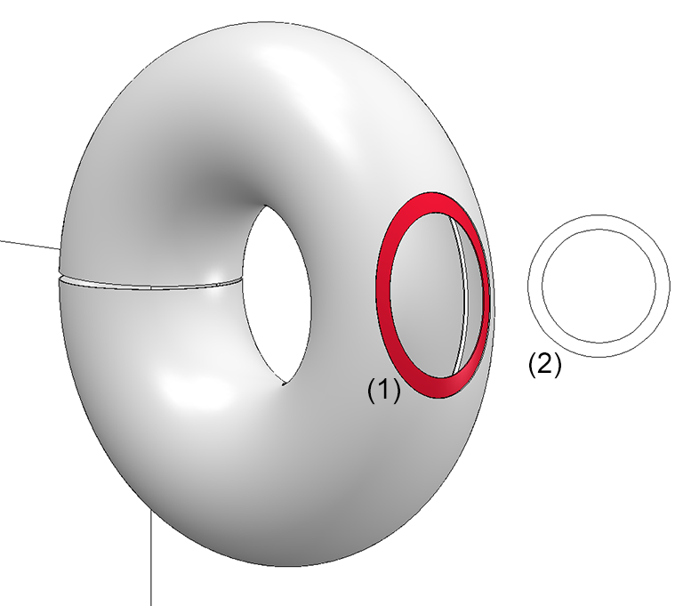
Facets lying on a torus can also be developed. This takes place approximatively by means of a double development, first with regard to the torus axes and then, once more, with regard to the cylinder axis resulting from this development. Therefore, the following warning message will be displayed: The development contains a torus that might not have been developed correctly. Please check the result!
(1) Facet
|
|
|
|
Use this function to start automatic sheet thickness calculation immediately after identification of the surface of a 3-D part (solid, freeform surface). After calculation of the surface thickness, the offset will be set, without any further entries, to half of the sheet thickness, i.e. the development takes place on the neutral axis. If the sheet thickness cannot be calculated, an input window appears. For freeform surfaces you always need to set the sheet thickness to 0.
The tear-open point determines the cutting line in the lateral surface.
You change the parameters of the tear-open edge in the system file ABWCOL.DAT. If you remove the "minus" preceding the parameters, the Layer, the Colour and the Line type will be evaluated. Kanteneigenschaften für Aufreißkanten beim analytischen Abwickeln; Schicht(0-999), Farbe(0-9), Stärke(0-9), Art(0-9); < 0:Kanteneigenschaften von Aufreißkanten werden nicht gesetzt [Edge properties for tear-open edges during analytical development; Layer(0-999), Colour(0-9), Weight(0-9), Type(0-9); < 0:Edge properties of tear-open edges not set] 1711
Facets lying on a torus can also be developed. This takes place approximatively by means of a double development, first with regard to the torus axes and then, once more, with regard to the cylinder axis resulting from this development. Therefore, the following warning message will be displayed: The development contains a torus that might not have been developed correctly. Please check the result!
(1) Facet |
|
 Please note:
To ensure an error-free production, e.g. during laser cutting, line elements must not be smaller than the laser beam. For this purpose you can specify a minimum line length in HiCAD. When developing circular arcs, for instance, this setting ensures that the circle segments will not fall below the specified minimum length.
You enter the minimum length in the ABWPAR.DAT system file at CAM-relevant minimum length of development.
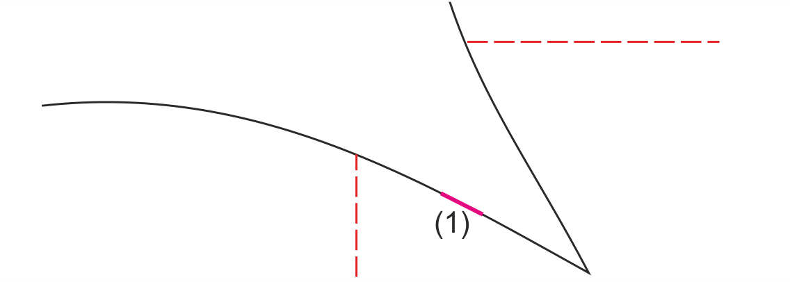
(1) Segment of an arc


Function Overview • General Information on Sheet Processing • Development Parameters
|
© Copyright 1994-2018, ISD Software und Systeme GmbH |


 When developing freeform surfaces, the sheet thickness always need to be set to