 > Develop sheets and export as DXF
 Sheet Metal > Sheet development > Extras >  > Develop sheets and export as DXF
 ![]()
This function exports the section contour or the development of Steel Engineering plates. in the process, one temporarily generated development will be output for the export. You can choose between various sheet development parameters. The orientation will only be unambiguous if it has been previously determined with the Processing direction function.
For the selection of the sheet development parameters the following options are available:

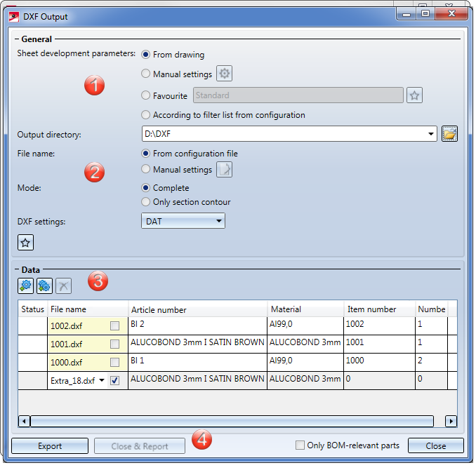
1. Sheet development parameters
1. General
2. Data
For the selection of the sheet development parameters the following options are available:
|
From drawing |
Use this option to load the parameters of the default settings |
|
Manual settings |
Clicking the |
|
Favourite |
The Favourites |
|
According to filter list from configuration |
Use this option to load the assignment of the development favourites to the part filters (Sheet Metal or Steel Engineering plates) from the Configuration Editor (at Sheet Metal > Sheet development > Filter-Development parameter assignment. Part filters are filters that have been predefined by the ISD and also the manual filters for part search that have been stored as Favourites. |
|
Output directory |
Here you enter the directory for the DXF files. Click on the folder icon |
|
File name |
Clicking on the The annotation settings can also be saved as Favourites. The file format is *.FTD. In the HiCAD SYS directory you will find the pre-configured file SheetToDXF.FTD. You load the file by activating the option From configuration file. |
|
Mode |
Here you specify whether only the section contours or the complete developments are to be exported. |
|
DXF settings |
For the DXF export you will need the file HCADACAD.DAT. This file contains:
The file can be customized and is located in the HiCAD SYS directory. After customization, do not save the file with the extension .DAT, but with .DA1, .DA2 or .DA3. For the export of developments to COBUS NCAD use the file HCADACAD_COBUS.DAT in the HiCAD SYS directory. If you want to use this file, save it with the matching file extension (e.g. HCADACAD.DA1).Click here for more information. |
|
|
The settings of the dialogue window can be saved as Favourites and reused at any time. To do this, click on the More on favourites management can be found in the Manage Favourites topic of the HiCAD Basics Help.
For the Management+BIM module you can preset the Favourites you defined here for the DXF export of external production drawings; namely, in the Configuration Editor at PDM > Management+BIM > External production drawings > DXF export Favourite. |
|
|
Use this icon to select the sheets for export in the drawing. |
|
|
This icon shows all sheets contained in the drawing in the export list. |
|
|
Use this icon to delete selected sheets from the export list. |
|
|
If the part attributes set in the Editor cannot be applied to the sheets, you have the option to enter your own file name. To do this, activate the checkbox and enter the file name. |
|
Only BOM-relevant parts |
If you have activated this checkbox, only developments the sheets of which consider the BOM-relevance among the part attributes will appear in the export list. |
The handling of item numbers can be determined in the Configuration Editor at Sheet Metal > Sheet development > Combine item number-wise. If you activate the checkbox  here, the development of the sheets with identical item number will only be exported once. The quantity will remain unchanged.
|
Export |
When you click on the Export button, temporary developments will be generated and output of all sheets in the export list, according to the specified parameters. The status icon |
|
Close & Report |
The Close & Report button activates the Report Manager and creates a BOM. If you did not itemize the Sheet Metal part in HiCAD, quantities will be set on 0 here.
To export a CSV file in the Report Manager, call the Settings |
|
Close |
Click this button to end the function. |
In the ABWPAR.DAT file you can suppress the export of chamfers and countersinks. For this to happen, you need to change the colour of the chamfered edges in the ABWCOL.DAT file beforehand. In the parameter:
Farbe der gefasten Kanten in der 2D-Abwicklung (-1 = wie Umriss)
enter, for instance, 7 for green. Then, change the following parameters in the ABWPAR.DAT file:
Consider non-contour edges for DXF export (1/0)
0
Consider thread lines for DXF export (1/0)
0
Then, restart HiCAD. The chamfers and thread lines will then no longer be considered for DXF export.
![]() Please note:
Please note:
If a countersunk bore is located at the edge of the sheet and HiCAD generates the development, it will always choose the smaller radius for the development. For chamfers the longer side will be selected.
In the SheettoDXF.ftd file you can find the default setting for the composition of the DXF file name.

|
© Copyright 1994-2018, ISD Software und Systeme GmbH |