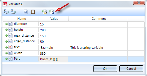
In the dialogue window for part variables new functions are available that allow you to export part variables as CSV file and to import them from a CSV file.
Shaded views can now be rotated much faster - especially shaded views with visible edges. Three different model drawings - consisting of 20.000, 60.000 and 90.000 parts, respectively, were submitted to performance tests. Some of these parts were highly complex, imported elements. Here are some concrete examples of the tested drawings:
20.000 parts with some large, imported parts (Image: TGM Kanis Turbinen GmbH, Nuremberg, Germany)
60.000 parts (Image: CAD Planung Arnold Matei, Mannheim, Germany)
Compared with HiCAD 2017, a significant increase of the frame rate (the number of images created during rotating) for the tested drawings could be achieved:
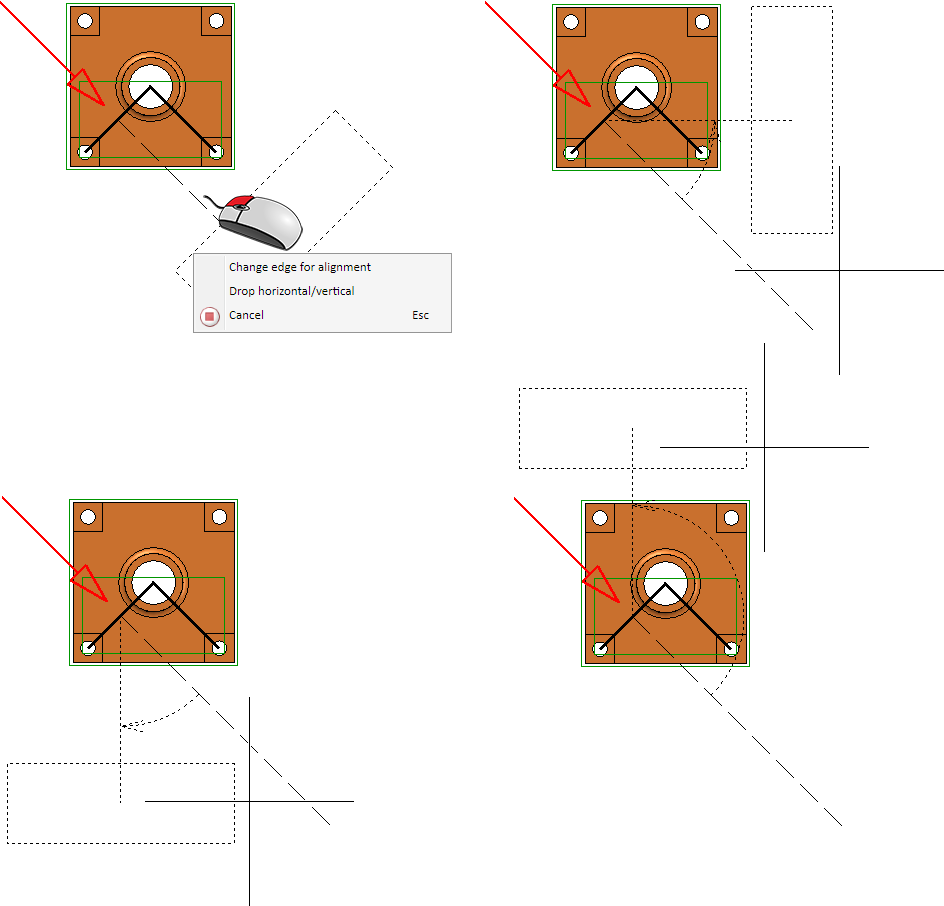
Sectional views can now also be dropped horizontally or vertically. For this purpose the context menu that you can open while the view is "attached" to the cursor has been extended accordingly.
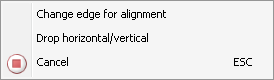
After calling the Drop horizontal/vertical function you can select the the rotation- upwards, downwards, to the left or right - with the cursor and drop the view. The viewing direction of the section will be determined in the moment of the function call, that is, it depends on the side of the reference edge on which you called the context menu with a right-click. The image below shows some different possibilities.
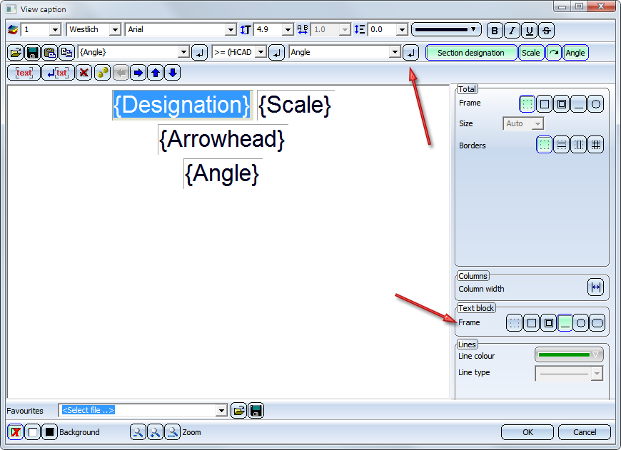
The View caption dialogue window has been redesigned.
 In older HiCAD versions (before HiCAD 2018 SP2) the underlining of text blocks will be ignored. Although the underlining will still be visible when loading the model drawing, and they can also be printed. But after updating the annotation the corresponding text blocks will be shown without frames.
All possible functions for exploded views can now be found in a new Ribbon.
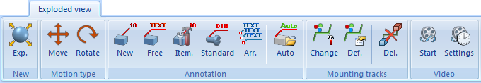
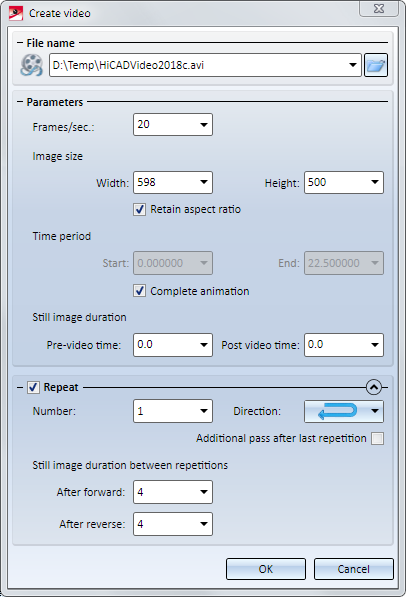
Use the new Video  function to save the creation of exploded views as videos (similar to Simulations).
New are the Mounting tracks functions in the same-named function group of the Exploded view Ribbon:
|
|
|
|
|
|
|
|
In the Exploded view docking window you can now open a new context menu. Right-clicking an item in the log of the exploded view, the following context menu will be displayed:
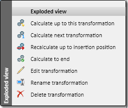
These functions enable you to partly or completely recalculate exploded views, e.g. after changes to the original model, or edit transformations.
|
|
Calculate up to this transformation The exploded view will be calculated up top the marked transformation. The insertion position will then be placed before the marked transformation. |
|
|
Calculate next transformation Only the transformation behind the insertion position will be calculated. The insertion position will then be placed after this transformation. |
|
|
Recalculate up to insertion position The exploded view will be calculated up to the insertion position. |
|
|
Calculate to end The exploded view will be recalculated completely. |
|
|
Edit transformation Use this function to edit the movements and rotations of an exploded view. When you call the function, a dialogue window will be displayed for this purpose. |
|
|
Rename transformation Use this function to rename transformations. |
|
|
Delete transformation This function deletes the transformation that was marked in the log. Multiple selections are also possible. |
Exploded views can be restored to normal views with the new Delete exploded layout  function. You find the function at Views > Representation > Shaded
  > ... and in the context menu at Representation > Others > ....
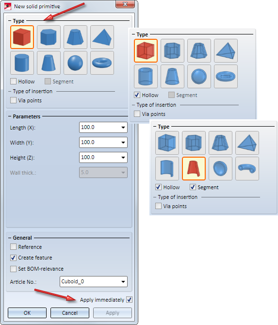
The New solid primitive dialogue window has been revised.
When using the Move+Rotate part, via fitting points function, the specification of the 3 fitting point pairs will now be graphically visualized. During fitting point specification in the model drawing, you can right-click to open a context menu with further point specification functions.
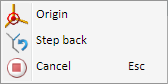
Use the Origin function to place the fitting point in the origin of the active coordinate system. Use the Step back function to select a new fitting point on the part
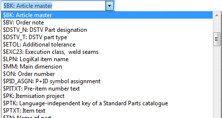
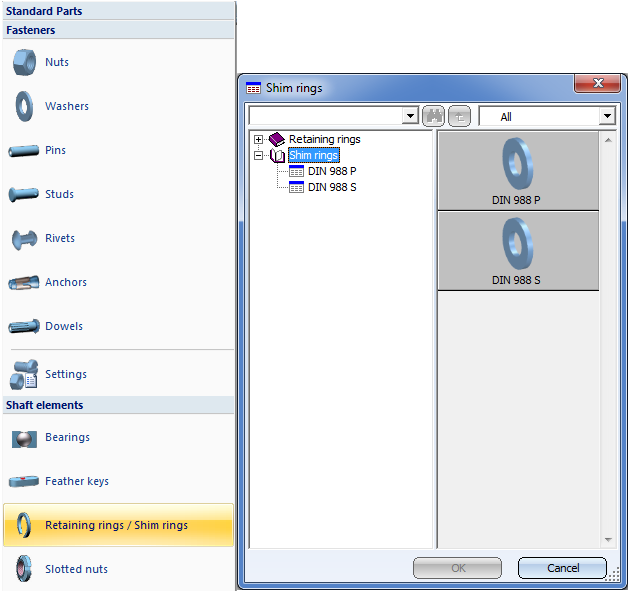
Shim washers could previously be found in the catalogue Fasteners > Retaining rings. As of HiCAD 2018 SP2 a separate catalogue exists for Shim rings. Therefore, the 3-D function 3-D Standard > Standard Parts > BoltScrew > Retaining rings has been renamed to 3-D Standard > Standard Parts > BoltScrew > Retaining rings / Shim rings.
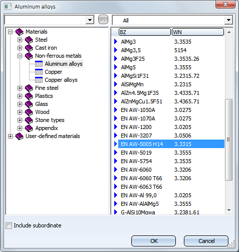
The material EN AW-5005 H14 has been added to the Aluminium alloys table (in the catalogue Materials> Non-ferrous metals).
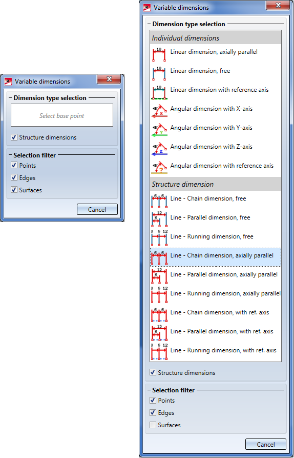
The variable dimensioning now also allows you to determine linear structure dimensions, i.e. chain, parallel and running dimensions. To do this, activate the Structure dimensions checkbox in the dialogue window.
In older HiCAD versions (before HiCAD 2018 SP2) the underlining of text blocks will be ignored. Although the underlining will still be visible when loading the model drawing, and they can also be printed. But after updating the annotation the corresponding text blocks will be shown without frames.
HiCAD 2018 SP2 supports display lists for the graphic preview of polygon models. Especially if there are many polygon models, e.g. in element installation drawings, a performance increase by a factor of up to 3 can be achieved (with a suitable graphic card).
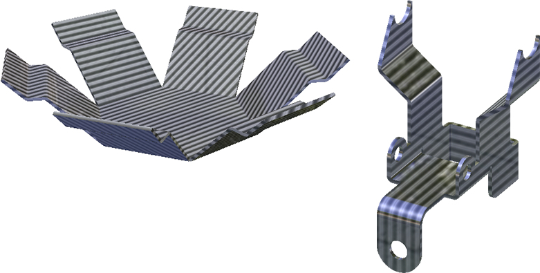
The applying of textures to individual sub-parts of Sheet Metal parts has been optimized in such a way that the result will be consistent both with regard to the alignment of the texture and the transitions between neighbouring parts.
This function searches, via the article master of the active part, a KRA file linked via HELiOS, and automatically exchanges the active part with the KRA file. In contrast to the functions Exchange 3-D part, via document master and Exchange 3-D part, via article master, no document or article selection and no placing of the exchanged part will be necessary here.
The function is particularly useful when you subsequently reference parts, for which a linked detail drawing already exists, in the assembly of the original model drawing. In this case it will be ensured that the part that exists in the detail drawing will be exchanged with the referenced part. HiCAD will also attempt to preserve the dimensions of the part to be exchanged.
Please note:
Here, "detail drawings" are not the detail drawings that are created with the Drawing derivation function on the Drawing tab, but manually created drawings which have either been created via Drawing > Save/Reference > Part and the Detail drawing... option, or by pasting of individual parts into a drawing file from the Clipboard. When using the Clipboard, please remember that dimensions will not be taken over.
When you call the function, HiCAD will check via the article master of the active part, whether a linked KRA file exists in the HELiOS database.
Click here to view an example.
Notes on dimension reconstruction:
If a part has sub-parts and if the detail drawing has been created with a version older than HiCAD 2018 SP1, dimensions cannot be reconstructed, i.e. they cannot be assigned to the corresponding parts. In this case you should open the Configuration Editor, go to System settings > Referencing and activate the Recover dimensions and weld symbols before calling the Exchange 3-D part, via DB link function. The dimensions and weld symbols will then be assigned to the superordinate part.
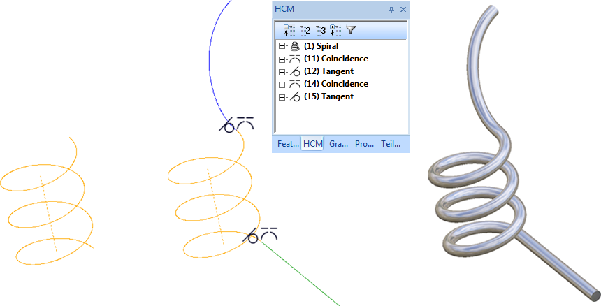
Spirals can also be used as guidelines for the C-edge sweep function. This is now even possible if further sketch elements have been attached to the start or end of the spiral. Please note however that in such cases these elements must have been linked to the start or end of the spiral via a Coincidence constraint!
In the example shown below, further edges have been added both at the start and at the end of a spiral. The start point of the edges lies in the start (or end) point of the spiral, where Coincidence constraints have been assigned. Then, the C-edge sweep function was used to place a circular cross-section along this "expanded spiral".
The dialogue of the Part variables  function has been largely adjusted to the one of the Part variables docking window.
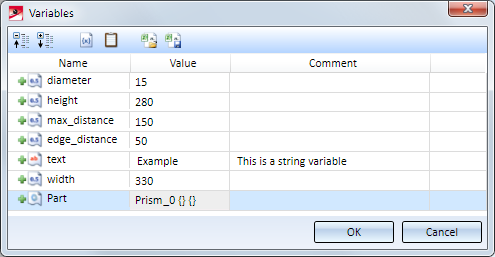
The dialogues for view variables and feature variables have been adjusted accordingly, too.
In the 3-D Standard > Tools > Crossh. > ... pull-down menu you can now find new functions that allow you to show and hide axes:
|
|
Hide axis - Individual Hides individual axes. Select the axes you want to hide. |
|
|
Hide axis - Group Hides a complete group of axes that form a crosshairs. For instance, if you select one axis of a crosshairs of a sphere, all axes will be hidden. |
|
|
Hide axis -All in active part Hides all axes / crosshairs of the active part. |
|
|
Show axis - All in active part Shows all axes / crosshairs of the active part again. |
The hiding of the axes is recorded in the Feature log in the form of an entry called Hide crosshairs.
If one of the Hide axis functions is applied to axes which have been automatically generated by a different processing (e.g. after insertion of a bore), this step will not be entered in the Feature log as a new feature, but as a sub-feature of the creation feature. In this way it is ensured that hidden axes will actually remain hidden after feature recalculations.
If you want to redisplay individual axes / crosshairs, right-click the Hide crosshairs entry in the corresponding feature and choose Clear. The corresponding feature entry will then be deleted.
To redisplay all axes / crosshairs of the active part in one step and simultaneously delete the corresponding feature entries, choose the Hide axis - All in active part function.
In the 3-D Standard > Tools > Point > ... pull-down menu you can now find new functions that allow you to show and hide points:
|
|
Hide point Hides individual isolated points. |
|
|
Hide points, active part Hides all isolated points of the active part. |
|
|
Show points, active part Shows all isolated points of the active part. |
The hiding of isolated points will be recorded in the Feature log, in the form of an entry called Hide isolated points. In this way it is ensured that hidden isolated points will actually remain hidden after feature recalculations. Right-click the feature entry and choose Clear to remove it and redisplay the point.
To redisplay all hidden points of the active part in one step and simultaneously delete the corresponding feature entries, choose the Show points, active part function.
The "Copy from part" function is no longer available. Instead, the selection menu of the Copy edges  function (open with a right-click after calling the function) now contains the new
 All lines or edges of part
option. You can use this option to copy all lines or edges of any 3-D part into the active part. In contrast to the old "Copy from part" function, the new function enters a feature called Isolated edges into the Feature log that contains the inserted edges.
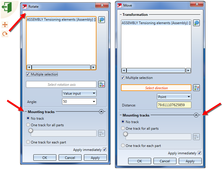
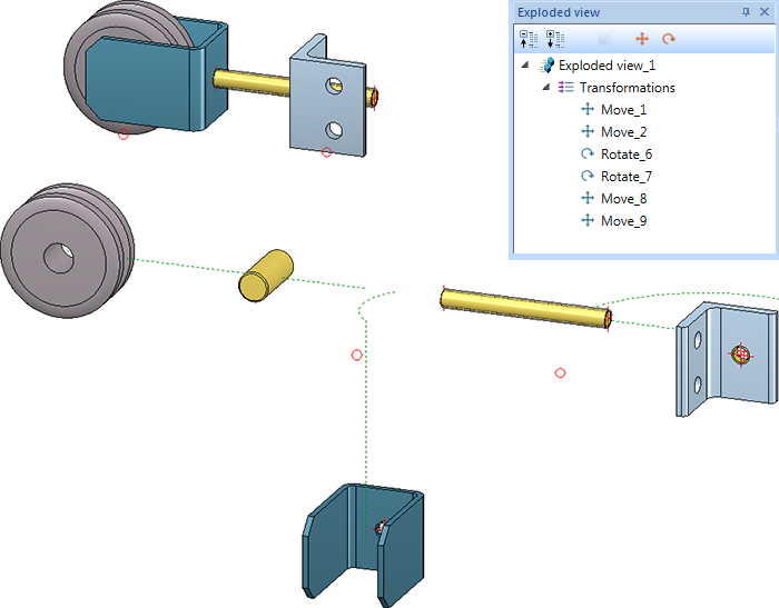
Example of an exploded view with displacements, rotations and mounting tracks
The former "Show/hide edges in view" function at Views > Properties has been renamed to Show/hide elements in view  . New in the dialogue window of the function is the Processing planes checkbox. By activating or deactivating the checkbox you can show or hide processing planes of the active view in one step.
Alternatively, you can access the functions in the context menu for views at Show/hide parts > Others:
|
|
Hide processing planes
|
|
|
Show processing planes
|
To open the context menu for views, right-click the pink dashed frame around the drawing object.
In shortened views, processing planes are not being shown - regardless of the setting in Show/Hide elements in view.
The "Delete coating line" function has been replaced with the Show/Hide coating lines  function. You find the function in the context menu for coating lines.
Coating lines can be hidden or shown in the active view or in all sectional views. One distinguishes between coating lines on the inner side and the outer side. When you call the function, the following dialogue window will be displayed:
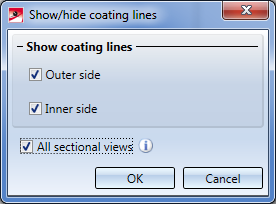
With the settings shown above, the coating lines will be shown in all sectional views on the outer side and inner side.
If all coating lines have been hidden, the lines can be redisplayed again via the context menu for sheets: In the sectional view, right-click the sheet and choose Properties > Coating line.
Via the variable dimensioning you can now also determine dimensions of the type
by selecting an edge or a surface.
If you choose Angular dimension with reference axis as dimension type, a reference axis needs to be specified. In such cases the Select reference axis button will be displayed in the dialogue window, and HiCAD will ask you to specify a reference axis - either by identifying an edge or by specifying 2 points. The dimension will then be attached to the crosshairs.
The selected reference axis will remain active until you select a different reference axis or end the function. This means that if you choose Angular dimension with reference axis in the dialogue again, the previously selected reference axis will be used again. If you want to use a different axis, click the Select reference axis button and specify a different axis.
The Change language of text  function on the 2-D Dimensions + Text tab can now also be applied to auxiliary texts in 3-D dimensions.
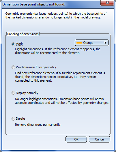
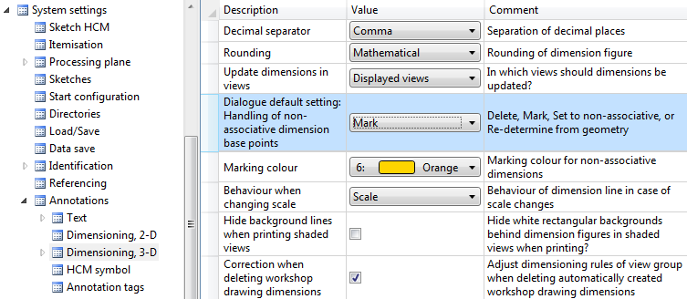
Dimension base points refer to geometric elements, e.g. surfaces, edges or points. If these elements are removed, the dimensions will lose their reference and will no longer be associative. In such cases the Dimension associativity - Update functions can no longer be carried out properly, and the Dimension base point objects not found dialogue window will be displayed. The dialogue window and the corresponding settings in the Configuration Editor at System settings > Annotations > Dimensioning, 3-D > Dialogue default setting: Handling of non-associative dimension base points have been revised in SP1.
The function Itemise part  now proceeds as Itemisation, individual parts
  (via Drawing > Itemisation/Detailing > Itemisation). This means i.a. that
conflicts with other positions can be identified.
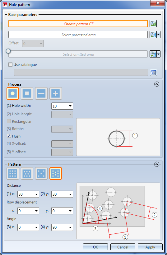
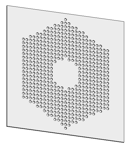
Now you have the option to integrate hole patterns in a sheet after adjusting the bend zone. Thus, the hole pattern (analogically to bores) can be applied even in accordance with multiple flanges and bending zones.
In the wake of this enhancement, the requirement that the processed area must be on the whole side, became no longer necessary.
Another new enhancement is that the usual features, such as Process sketch and Create new sketch in plane are also accessable via the dialogue window Hole pattern for working with processed and omitted areas.
Furthermore, the function Hole Pattern is only accessable via the Ribbon 3D-Standard; the entry on the ribbon Sheet Metal has been removed. However, the function is still applicable on sheet metal.
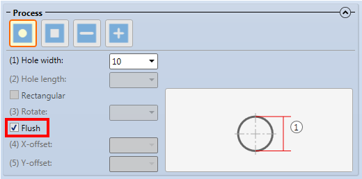
Previously the start hole for insertion of hole patterns was always placed flush on the right and above the origin of the Pattern CS. As of version HiCAD 2018 SP1 the dialogue window offers the additional Flush checkbox. If you deactivate this checkbox, the start hole will be placed centrally into the origin.
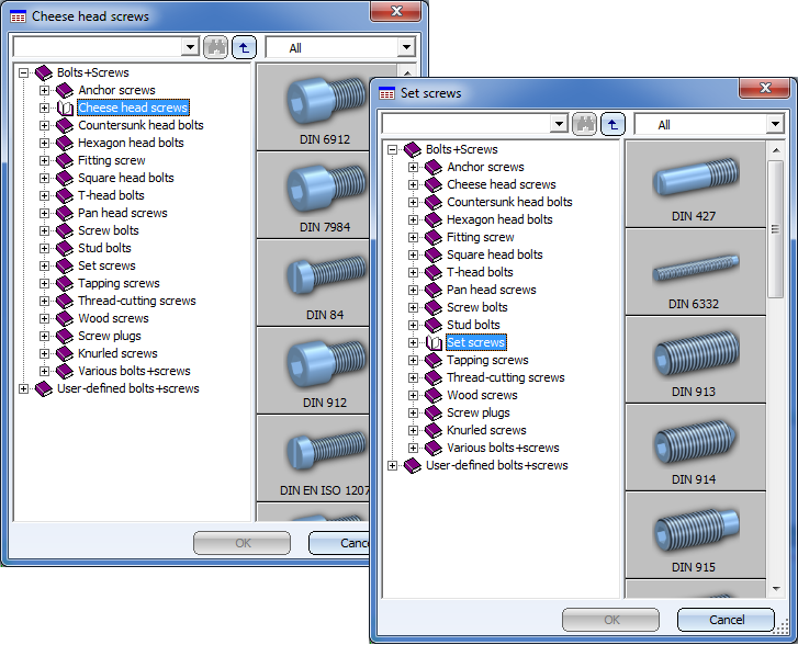
The tables of the HiCAD Standard parts catalogues are to contain new preview images and descriptive detail graphics. In the first step these were implemented for the Fasteners catalogue. The same which will soon be done for the other catalogues.
In previous versions, various settings for texts and annotations could be found in the system file TXTPAR.DAT. As of HiCAD 2018 this file will no longer be available. Instead, the settings are specified in the Configuration Editor. The corresponding setting options can be found at
Threads in shaded views can be represented either with thread texture or transparently. The representation can be predefined via the configuration management under Visualisation > Views with the parameter Thread representation in shaded views.
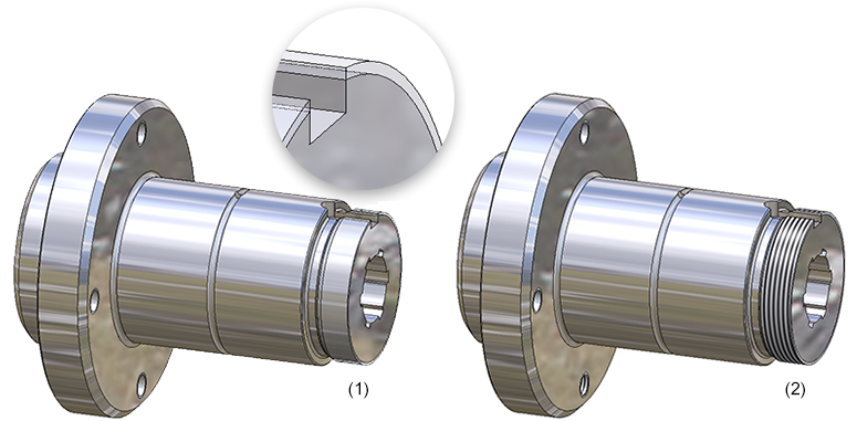
Flanged shaft - (1) Transparent view, (2) With thread texture
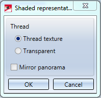
Irrespective of the default setting in the Configuration Editor, the thread representation in shaded views can be determined separately for each view. For this, use the function Shaded representation via Representation > Views > Shaded repr...
|
|
Shaded representation (Active view) With this function, the active view of thread representation can be changed. For that, the dialogue window Shaded representation is shown:
Choose the desired representation by clicking the respective option and close the window by clicking OK. |
|
|
Shaded representation (All views) This function complies with the function for Active viewbut affects all views of the model. |
Only one thread will be equipped with texture in case of multiple insertion via grid.
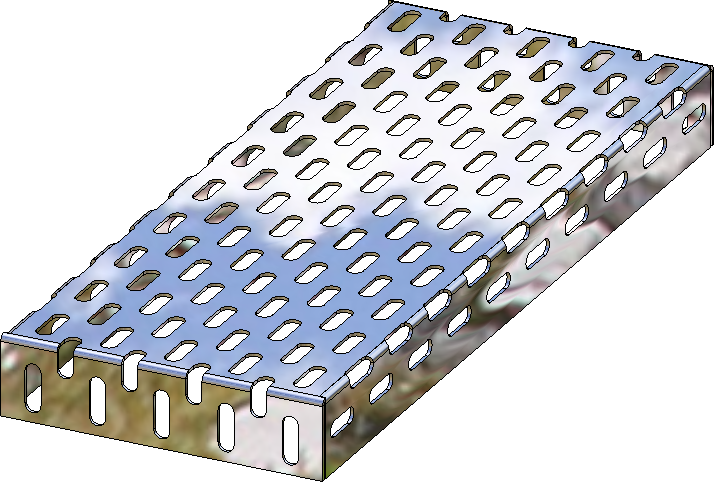
HiCAD 2018 allows a generation of sheets and plates with hole patterns according to DIN 4185-2 and DIN 24041. These are sheets/plates with identical holes arranged in regular patterns, which can, for instance, be realized by punching or drilling tools. Possible hole types are round holes, square holes, slots and special holes. The holes can be arranged in straight, staggered, diagonally staggered or freely staggered rows. You have a choice between the selection of predefined holes and hole patterns according to DIN from a catalogue, or the use of self-defined holes and hole patterns. In the process, the holes will only be placed within a freely defined area if they stay within its limits. In addition, an area for the omission of holes can be defined.
You find the function at 3-D Standard > -Standard Processings > Bore > Hole pattern  and Sheet Metal > Further Tools > HoleP .
The Optimise part  function can now no longer be applied to individual surfaces, but only to the active part or to the entire model drawing.
Various part creation functions could only show the article number in upper case letters. The functions shown below now also allow a spelling of the article number in upper or lower case letters:
|
3-D Standard |
3-D FFS |
||
|---|---|---|---|
|
|
Solid primitive |
|
|
|
|
|
||
|
|
|
||
|
|
|
|
|
|
|
|||
|
|
|||
|
|
|||
|
|
|||
If one of the Delete crosshairs functions is applied to a crosshairs that has been automatically created by a different function, e.g. the insertion of a bore, this deletion will not be entered as a new feature, but as a sub-entry called Delete crosshairs beneath the creation feature:
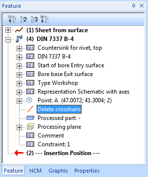
This change will also be preserved in case of a recalculation. To delete this processing step later, right-click the Delete crosshairs entry and choose Clear.
Up to HiCAD 2017 the deletion of isolated points was not considered in the Feature log, causing an unwanted restoring of deleted points in the drawing after feature recalculation.
From HiCAD 2018 onwards the deletion of isolated points will also be considered in the log of their respective creation Feature. If an isolated point is deleted in the drawing, the corresponding entry will also be deleted in the Feature log. After a recalculation, the deleted point will remain deleted.
Please also note that you can now also directly choose during development of sheets whether you want isolated points of the Sheet Metal part to be shown or hidden. The setting concerns only the isolated 3-D points that the Sheet Metal part provides. The display of these points can be changed in the Feature of the sheet development. If an isolated point of the Sheet Metal part is deleted, this point will also be removed from the development when it is synchronized with the part. Isolated points that have been created in the development subsequently are always visible.
The 3-D Standard > Tools > Edge > ... pull-down menu has been revised.
The functions
have been combined into one new function called Copy edges . After calling the function, right-click to open a context menu with various options:
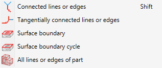
The new function is also supported by Feature Technology: In contrast to the old functions, for edges that are taken over with the new function a Feature called Isolated edges will be created.
The Variable dimensioning function now also allows the detection of Linear dimensions with reference axis. If you choose this dimension type, you need to specify a reference axis. To do this, click on the Select reference axis button. HiCAD will then prompt you to select a reference axis, either by identifying an edge or specifying 2 points. The dimension will then be attached to the cursor.
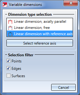
The selected reference axis will remain active until you select a different reference axis or end the function, i.e. if you select the dimension type Linear dimension with reference axis in the dialogue window again, the previously selected reference axis will be used. If you want to select a different axis, click on the button and define the new axis.
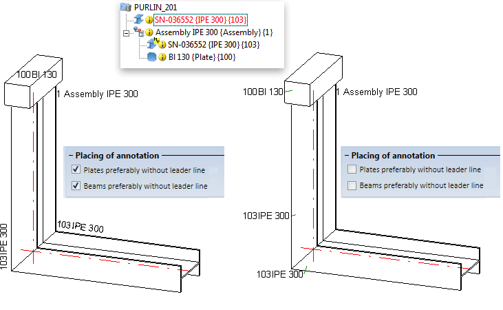
The Automatic part annotation now allows you to determine whether the annotations for beams and plates are to be applied with or without leader line.
For this purpose the dialogue window has been expanded accordingly:
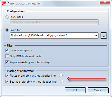
If this checkbox is active, HiCAD proceeds as follows: If there is enough space on the part, the annotation for the plate will be placed directly on the part. If there is not enough space, the annotation will be created with a leader line.
If this checkbox is active, HiCAD proceeds as follows: If there is enough space in the vicinity of the part, the annotation will be placed along the beam as shown below. If there is not enough space, the annotation will be created with a leader line.
Like the Automatic part annotation function, the Optimize arrangement  function now allows you to determine whether the annotations for beams and plates are to be applied with or without leader lines.
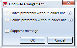
For plates and beams you can determine (as with the automatic part annotation) whether the annotations for beams and plates are to be applied with or without leader line.
If this checkbox is active, HiCAD proceeds as follows: If there is enough space on the part, the annotation for the plate will be placed directly on the part. If there is not enough space, the annotation will be created with a leader line.
If this checkbox is active, HiCAD proceeds as follows: If there is enough space in the vicinity of the part, the annotation will be placed along the beam as shown below. If there is not enough space, the annotation will be created with a leader line.
The last specified settings that have been confirmed with OK will be the default settings when the function is called again.
The Exploded view  function has been revised completely.
This function enables you to display the active view as a so-called "exploded view". This type of view shows the part and assemblies of the model drawing in "dismantled" state, with the dismantling being based on a translatory displacement of the parts. Exploded views are saved together with the geometry in the .SZA file. Since all part displacements are recorded in an explosion log, they can be changed subsequently if required.
Proceed as follows to define an exploded view:
![]()
All displacements of the exploded view will be logged. The log is shown - similar to the Feature log - in the Exploded view docking window. Via this docking window you can change exploded views subsequently.
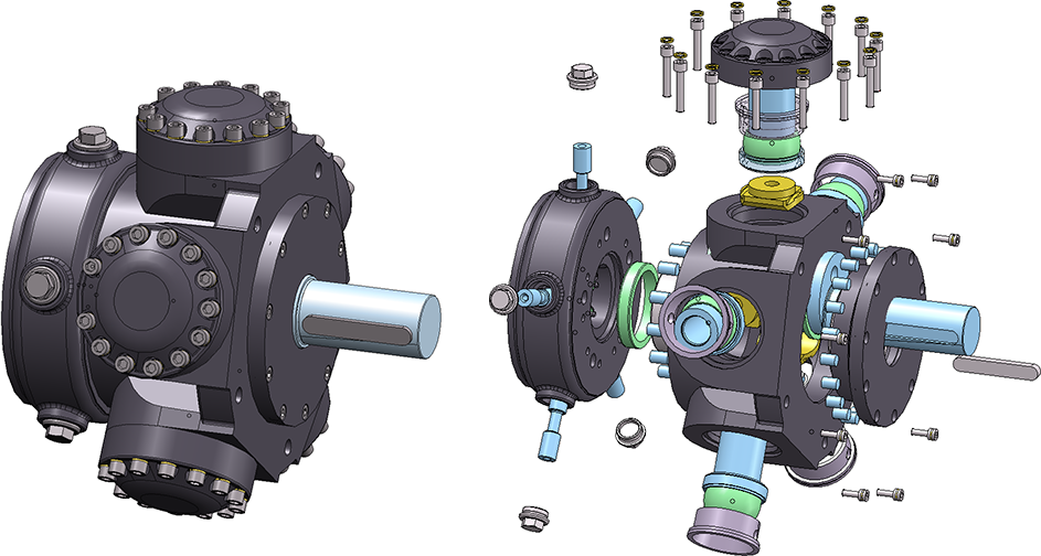
Example of an exploded view (some of the lids have been excluded here)
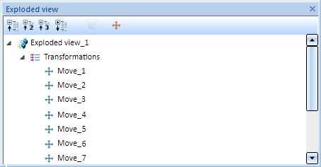
The "Exploded view" docking window
The dialogue window for Sectional views has been expanded.
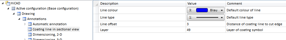
For Sheet Metal parts you have now the option to specify whether the coating in the sectional view is to be shown or not, by activating or deactivating the Display checkbox beneath Coating in the dialogue window. The coating is displayed in the form of an offset edge, the so-called "coating line". The settings for the representation of the coating line can be found in the Configuration Editor at Drawing > Annotations > Coating line in sectional view.
The representation of the coating line can also be changed subsequently. To do this, right-click on the coating line in the required view and choose the desired function in the Coating symbol context menu:
|
Function |
|
|---|---|
|
|
Change coating line parameters Use this function to change the colour, line type and layer of the coating line. When you call the function, the 3-D edge parameters dialogue will be displayed for this purpose. |
|
|
Change offset distance Use this function to change the offset distance, i.e. the distance between coating line and cut edge. |
|
|
Delete coating line Deletes the coating line. |
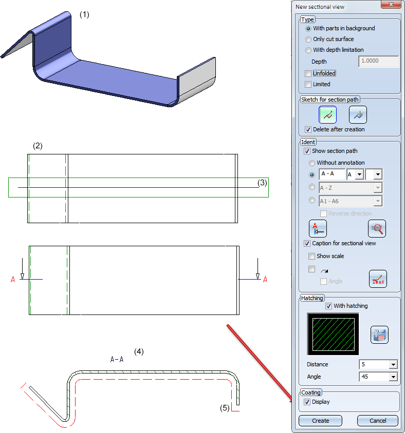
Sheet Metal part (1) with outside coating; Top view (2) with cut edge (3), Sectional view (4) with coating line (5)
Please note:
At Views > Representation > Shaded > ... you can find the following new functions:
|
|
Shaded representation (Active view) Use this function to change the representation of threads and switch panorama mirrorings on or off in active views.
Here you can specify whether you want thread to be displayed with thread texture or transparent by activating the desired option. HiCAD offers the option to simulate environments by assigning a panorama to a Sheet or Model area. The surfaces of shaded models will then mirror this panorama, i.e. their environment. Activate the Mirror panorama checkbox to switch this effect on, deactivate it to switch it off again. |
|
|
Shaded representation (All views) This function corresponds to the same-named function beneath Active view, with the difference that it affects all views of a model drawing. |
In this way, panorama mirrorings can now be switched on or off separately for each view.
The formerly available functions Mirror panorama  and Do not mirror panorama
  are no longer available in HiCAD 2018.
If referenced parts have part attributes which are not to be updated on a regular basis, the synchronization can also take place in a specific, targeted way. In previous versions this behaviour was determined in the system file ref3d_attr_akt.dat, and from now on in the Configuration Editor at System settings > Referencing > Synchronization of attributes.

Click the  symbol to activate a table in which you can specify for each part attribute
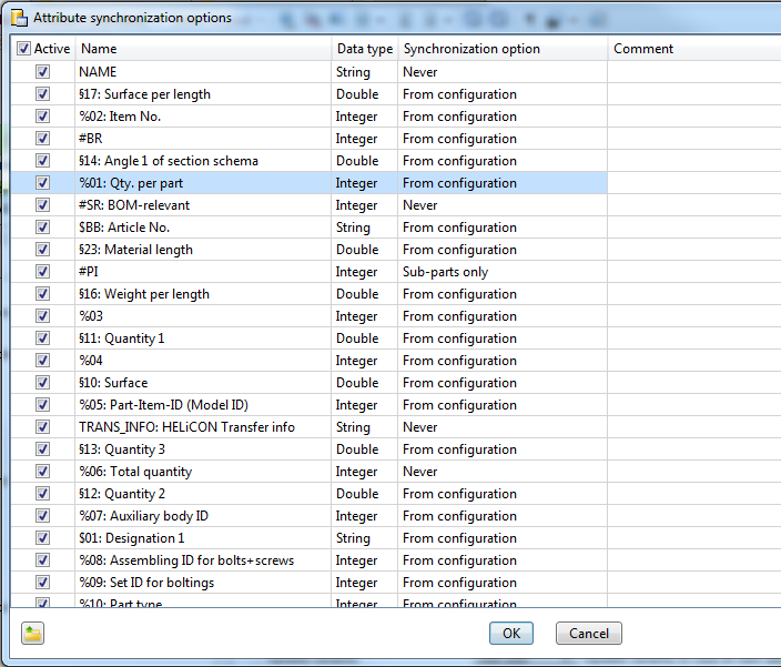
ISD default settings (detail)
For this to happen, a row that is composed as follows must exist for the corresponding part attribute:

|
Active |
Via the checkbox of this column you determine whether the synchronization is to be carried out or not. If you want to activate or deactivate all check boxes in one step, then activate or deactivate the check box in the column heading, e.g. As an alternative, you could also use the context menu's function for activation by clicking the right button on a table entry. |
|
Name |
Here you enter the name of the attribute. Attributes predefined by the ISD can also be chosen via a selection box. To do this, double-click on the corresponding row and choose the attribute from the list.
|
|
Data type |
Here you select the attribute type (double-click on the row):
|
|
Synchronization option
|
Here you select the type of the synchronization. The following options are possible:
|
|
Comment |
Here you can enter a comment. |
To insert further attribute rows, scroll to the end of the table. There, click on the empty row and specify the required settings. Proceed likewise for further rows. Click OK to close the Attribute synchronization options dialogue window.
The sorting of the table can be changed by clicking on a column header.
With a right mouse click on a table entry you activate the context menu, in which you are enabled to delete the active table row as well as activate or deactivate all check boxes of the column active.
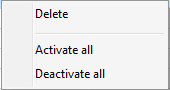
Please note:
Up to HiCAD 2017 the settings for attribute synchronization were defined in the system file REF3D_ATTR_AKT.DAT. If you want to take over settings from an existing REF3D_ATTR_AKT.DAT file, this can be done via the Open file  button. After selecting the file, the settings shown in the Attribute synchronization options dialogue window will be overwritten with those of the selected file after closing the dialogue window with OK.
If you have applied any changes to the file REF3D_ATTR_AKT.DAT, please save the file before making an update.
The updating of referenced 3-D parts with many HCM dimensions has been speeded up significantly.

|
© Copyright 1994-2018, ISD Software und Systeme GmbH |


 .
.