Basics - What's New?

Discontinuation of Windows 7 ®
Microsoft will cease the support for Windows by January 2020. Due to compatibility matters HiCAD 2020 SP2 and HELiOS 2020 SP2 will thus be the final versions of our CAD and PDM systems which support Windows ® 7. The corresponding server operating systems (Windows Server 2008 R2 or older) will then no longer be supported either.
Discontinuation of “old“ HiCAD itemisation
As of HiCAD 2019 the “old” itemisation, i.e. the itemisation that was used up to HiCAD 2017, will only be available for model drawings that were already itemized with these functions. From HiCAD 2021 onwards, only the “new” itemization will be supported.
Discontinuation of "old" OpenGL versions
From HiCAD 2021 on, only OpenGL version 4.3 is used in all HiCAD modules. Until now this was only the case with the module HiCAD Point Cloud. This means that HiCAD 2021 can only be run on computers whose graphics card supports OpenGL Version 4.3 or higher. Please also read the corresponding notes shown below.
Discontinuation of the old figure format (FIG)
Since HiCAD 2017 we have been supporting FGA as figure format (before FIG). Starting with HiCAD 2021 (Version 2600.0), we assume that the figures stored in HELiOS have been converted to the new format, or convert the still existing figures automatically as part of the database sub-version update to Version 2600.0.
Service Pack 2 2020 (V 2502)
Licensing
The basic module HiCAD Education Edition premium for schools and teaching institutions also includes the extension module HiCAD Point Cloud from HiCAD 2020, SP2, Patch 1 onwards.
The new Renderer - Update to OpenGL Version 4.3
HiCAD uses OpenGL for graphics output - so far in Version 2.0. As already announced, starting with HiCAD 2021 only OpenGL version 4.3 will be used in all modules. Up to now this was only valid for the HiCAD Point cloud module. This means that HiCAD 2021 will only run on computers whose graphics card supports OpenGL Version 4.3 or higher. The use of onboard cards is also still possible - provided they meet the corresponding requirements. However, we recommend not to use them from HiCAD 2021 on, since the performance of these chips is insufficient for large and complex model drawings.
Decisive factors in the development of the new Renderer were the extended range of functions for the graphics output through the use of newer OpenGL functions, and the possibility to realize noticeable performance improvements in the graphics output in the future. With HiCAD 2021, the graphics output will be generally accelerated, which is reflected in a higher frame rate (frames/second). Viewing functions such as zooming, rotating or panning are thus significantly faster and appear even more fluid.
In order to give you the opportunity to get to know the new Renderer in advance, it is already delivered with Service Pack 2 for HiCAD 2020 and can be activated on a computer-related basis if required. It already offers significant performance optimizations in particular situations.
|
Our request: If you are updating to HiCAD 2020 SP2, you should also - at least on some workstations - activate the new Renderer (if the graphics card supports OpenGL 4.3). With HiCAD 2020 SP2 you still have the possibility to switch between both Renderers. This way you can help to detect possible problems with the new Renderer at an early stage. Of course, this renderer has already undergone extensive testing as part of our quality assurance process, but its use in daily practice can provide us with further important information. This will ensure that future updates to HiCAD 2021 or newer versions can be carried out smoothly. We thank you in advance for your kind support! |
Proceed as follows to activate/deactivate the new Renderer:
To switch between the old and new Renderer you first have to adjust the Windows Registry as follows:
In the Registry, switch to Computer\HKEY_CURRENT_USER\SOFTWARE\ISD Software und Systeme\HiCAD 2020.
Right-click on the Feedback entry there and create a new entry of type DWORD value (32Bit) called BetaRendererActivation.
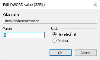
Supported are the following values:
|
0 |
The setting from the Configuration Editor will be used - System settings > Graphic > Use OpenGL Beta Renderer |
|
1 |
The new Renderer will be activated - regardless of the setting in the Configuration Editor |
|
2 |
The new Renderer will be activated - regardless of the setting in the Configuration Editor |
GUI and operation
New Autopilot Settings toolbar
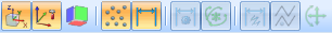
The Autopilot Settings toolbar at the bottom of the HiCAD user interface can now be used to control which points the Autopilot offers as snap points. Switching is possible at any time - even during the execution of a function. In the toolbar the possible snap points are highlighted in colour.

Using this bar you can control which point options should be visible on the Autopilot by activating / deactivating the symbols. For example, if you click on  , the snapping of isolated points is deactivated.

The currently selected Autopilot settings apply to the active HiCAD session. Which settings should be active when restarting HiCAD can be defined in Configuration Editor at System settings > Identification with the parameter List of point snap options.
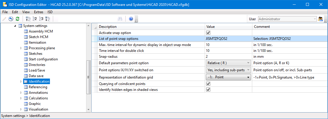
The ISD default setting is JISMTZFQOS2, i.e. snap points are isolated points, end points, genuine intersection points, centre points, tangential points, centroids, perpendicular base points, quad points, on-line points and theoretical intersection points.
If you click on the  symbol in the Autopilot Settings toolbar, the settings from the Configuration Editor are restored to defaults.
![]() Please note:
Please note:
- The Autopilot Settings apply to 2-D and 3-D point options.
- Point options that are deactivated from the active function cannot be activated in the Autopilot Settings either.
- The Autopilot Settings toolbar can be activated/deactivated via
 Settings > Toolbars.
New Visualisation toolbar
The previous toolbar "CS display" has been extended with additional functions for fast fading in and out of objects and renamed Visualisation. With the functions of this toolbar you can switch on or off the visibility of coordinate systems, isolated points, dimensions, HCM constraints etc. with one click. In certain situations - especially with large model drawings - this can make editing easier. For example, you can hide all dimensions of a model drawing without having to call a function in the context menu or ribbon first.
The following functions are new here:
|
|
Toggle visibility of isolated points (Drawing) All isolated points of the model drawing can be shown or hidden with one mouse click. |
|
|
Toggle visibility of dimensions (Drawing) All 2-D and 3-D dimensions of the model drawing can be shown or hidden with one mouse click. This applies both to drawing dimensions and parametric dimensions. |
|
|
Toggle visibility of dimensions (3-D Part HCM) |
|
|
Toggle visibility of constraints (3-D Part HCM) |
|
|
Toggle visibility of degrees of freedom (3-D C-Edge HCM) |
|
|
Toggle visibility of dimensions (3-D C-Edge HCM) |
|
|
Toggle visibility of constraints (3-D C-Edge HCM) |


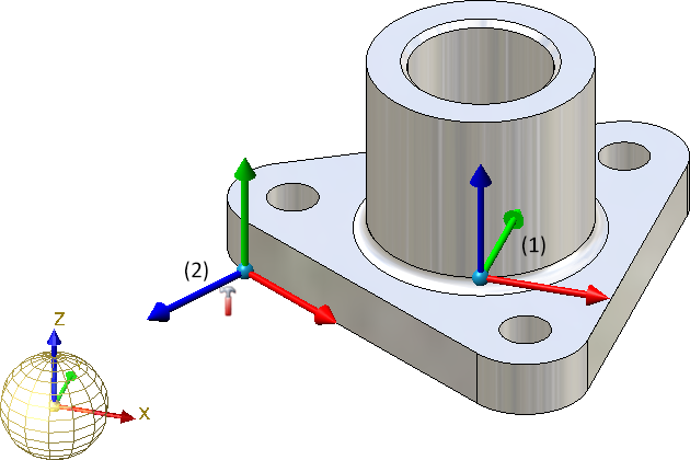
CS display - Fitting CS
The spatial representation of the Fitting CS (2) has been revised to make it easier to distinguish it from the Part CS (1).
New symbol for part with free edges
In the part structure display of the ICN the symbol for Part with free edges has been changed. The new symbol looks like this: 
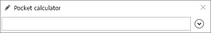
New pocket calculator
The HiCAD Pocket calculator has had a redesign.
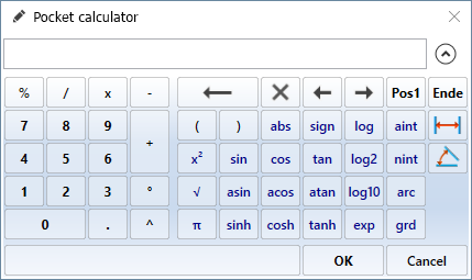
In many cases, HiCAD suggests a default value, which you can apply directly or correct.
You complete your input by
- pressing the left mouse button or
- pressing the ENTER key of the keyboard or
- clicking on the OK button.
Special keys:
|
|
Is used to take distances and angles from existing construction objects. Alternatively, you can also call these functions in the context menu, which you activate by pressing the right mouse button in the input field of the calculator. The functions of the distance and angle menu displayed here are the same as the identically named functions in the Information menu. The 3-D Distances menu also provides the Tracing lines function, which enables you to transfer the spacing of the tracing lines of a steel engineering beam. |
|
|
Hides the keyboard area of the pocket calculator.
|


Docking windows - Zooming of contents
The contents of various docking windows can be enlarged or downsized dynamically by zooming. This is possible for the following docking windows:
- Views,
- 2-D/3-D Part structure,
- Feature,
- HCM (2-D) und HCM (3-D),
- Part variables,
- Exploded view.
|
|
Zoom contents of one docking window To enlarge or downsize the contents of a single docking window, point the mouse cursor inside the window and turn the mouse wheel while holding down the CTRL key. |
|
|
Zoom contents of all docking windows To enlarge or downsize the contents of all docking windows, turn the mouse wheel while holding down the CTRL and the SHIFT key. |
|
|
Reset zoom The zoom of the active window can be reset by pressing the CTRL and middle mouse button simultaneously. To reset the zoom of all windows, press CTRL, SHIFT and the middle mouse button accordingly. |


Easier element snap
As long as no function is active, pressing and holding the SHIFT key from SP2 on automatically activates the element snap function - independent of the selected identification mode. This provides faster access to the context menus of individual geometry elements and is also a practical way to find a Feature in the ICN from within the geometry - especially in large and complex model drawings.

North American scale
Scales are used in HiCAD as
- Main scale of a model drawing,
- Scale of a view,
- Scale of a 2-D part and
- Scale of steel construction part drawings.
The scale can be selected from a selection box in the corresponding HiCAD function dialogues. In addition, in many cases it is also possible to enter a scale directly. The scales available in the selection boxes of the HiCAD functions are defined in the file szene-massstab.txt in the HiCAD subdirectory makro2d or for steel construction component drawings in the file StbEtZng_MASSSTAB.DAT in the HiCAD subdirectory sys. Please note that HiCAD supports the European scale logic by default, i.e. scale specifications in the form n:m, e.g. 1:1, 1:10, 5:1 etc.
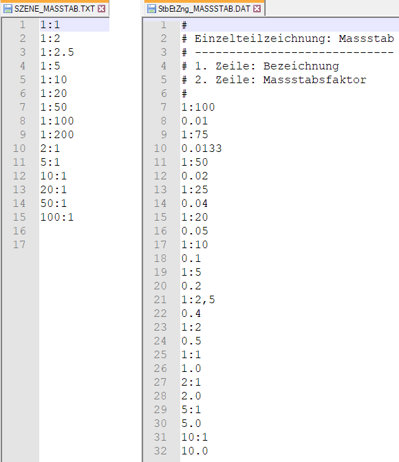
Default scales
However, the US scale logic differs from that in Europe. Therefore HiCAD offers the possibility to extend the above mentioned files by defining additional scale specifications. For examples of typical scale specifications in North America, refer to the following table:
|
1/128"=1'-0" 1/64"=1'-0" 1/32"=1'-0" 1/16"=1'-0" 3/32"=1'-0" |
1/8"=1'-0" 1/4"=1'-0" 3/8"=1'-0" 1/2"=1'-0" 3/4"=1'-0" |
1"=1'-0" -1/2"=1'-0" 3"=1'-0" 6"=1'-0" 1'-0"=1'-0" |
' foot, " Inch, 1 foot = 12 inches, 1 inch = 2,54 cm
|
Conversion table |
||
|---|---|---|
|
Scale |
Factor |
Decimal |
|
1'=1'-0" |
1:1 |
1.0 |
|
6"=1'-0" |
1:2 |
0.5 |
|
1-1/2"=1'-0" |
1:8 |
0.125 |
|
1"=1'-0" |
1:12 |
0.08333 |
|
3/4"=1'-0" |
1:16 |
0.06250 |
|
1/2"=1'-0" |
1:24 |
0.41667 |
|
3/8"=1'-0" |
1:32 |
0.031250 |
|
1/4"=1'-0" |
1:48 |
0.020833 |
|
3/16"=1'-0" |
1:64 |
0.015625 |
|
1/8"=1'-0" |
1:96 |
0.010417 |
|
3/32"=1'-0" |
1:128 |
0.007813 |
|
1/16"=1'-0" |
1:192 |
0.005208 |
|
1/32"=1'-0" |
1:384 |
0.002604 |
|
1/64"=1'-0" |
1:768 |
0.001302 |
|
1/128"=1'-0" |
1:1536 |
0.000651 |
Changing the file szene-massstab.txt
To structure the file, any number of empty lines and comments can be inserted, whereby comment lines must begin with the character #. Each scale specification must be in a separate line. The following notations are supported for the scale specification:
|
Notations |
Examples |
|
|---|---|---|
|
Specification in scale format n:m |
1:10 1:1 2:1 5:1 |
|
|
Specification as factor |
0.1 1 2 5 |
|
|
As factor with display text The factor is at the beginning of the line, the display text in brackets behind it. The display text is used by HiCAD in dialogues and information outputs. |
2.5 (2‘-6“ = 1‘-0“) 1 (1`-0“ = 1‘-0“) |
|
|
4. |
In scale format with display text The scale is at the beginning of the line, the display text in brackets behind it. The display text is used by HiCAD in dialogues and information outputs. |
1:12 (1“=1‘-0“) 1:48 (1/4“ = 1‘-0“) |
The notations 3 and 4 can be used to define US scale specifications, for example.
Example of an expanded szene-massstab.txt file
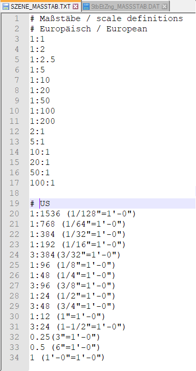
Further information can be found in the Definition of Scales topic.
Enhanced HiCAD VI / AV module
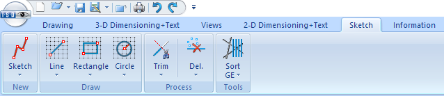
With the HiCAD VI / AV Viewer solution, HiCAD drawings and also and drawings imported via interfaces can be visualised. Furthermore, the module supports the plot generation/output and data export. In order to support the creation and editing of sketches for sectional and detailed views, the corresponding functions are now available on the Sketch Ribbon tab.
|
Functions |
Effect |
Sub-menu functions |
|
|---|---|---|---|
|
|
and sub-menu functions |
Allows you to draw a new sketch |
|
|
|
and sub-menu functions |
Inserts polylines, tangents and straight lines |
|
|
|
and sub-menu functions |
Inserts rectangles and polygons |
|
|
|
and sub-menu functions |
Inserts full circles |
|
|
|
and sub-menu functions |
Trims/edits sketch elements |
|
|
|
Delete lines and isolated points and sub-menu functions |
Deletes line elements and points |
|
|
|
and sub-menu functions |
Sorts graphical elements of the active sketch and provides further tools |
|


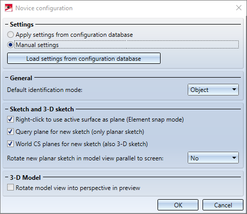
Novice configuration - - Settings for sketches
The settings for sketches in the Novice configuration previously only affected the creation of new sketches with the New sketch in plane and New 3-D sketch functions, and the functions at 3-D Standard > Process with sketch. However, they did not apply to other functions that use sketches to create or process parts, and also allow you to create new sketches. Here, the sketch plane was always the XY-plane of the world coordinate system.
As of SP2, the behavior when creating a new sketch has been standardized, that is, the settings of the Novice configuration dialogue window affect not only the creation of new sketches with the New sketch in plane and New 3-D sketch functions, but also all functions that use sketches to create or process parts, as well as all functions that allow you to create new sketches. This applies to such functions as Add and Subtract, deriving sheet metal parts from sketches, element installation, and much more. This also allows these functions to query the determination of the sketch plane before creating a new sketch
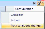
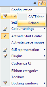
Track catalogue changes
Up to now, the Configuration Editor at System settings > Catalogues could be used to define how catalogue changes should be handled in HiCAD. From HiCAD 2020 SP2 onwards these settings are no longer available in the Configuration Editor . Instead, the switch Track catalogue changes is now available at  Settings in the Catalogue menu.
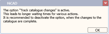
If the switch is active, the catalogues are regularly checked during a HiCAD session to ensure that they are up-to-date. This actuality check can, however, significantly impair performance in some situations. If the switch is active, then this is indicated when HiCAD is started. By default, the switch is inactive by default, that is, the catalogues are loaded in HiCAD only once, when starting HiCAD. After that, the system does not check whether more recent data is available. To update the catalogues after changes, the function Reload is available. This offers the possibility to update catalogues after changes without having to leave HiCAD and without having to accept performance losses due to the constant check for up-to-dateness.
The current status of the switch (active/inactive) is entered into the Windows Registry. If the switch is active, the following message is displayed when starting HiCAD.
Drawing derivation
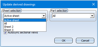
Update derived drawings - active sheet
When updating derived drawings, it is now easier to update the active sheet. The selection box has been extended accordingly.
Change settings - Rearrange views
If the settings were changed in an existing workshop drawing and then the drawing was updated, HiCAD always rearranged all views. From HiCAD 2020 SP2 onwards this can be set individually. For this purpose the Rearrange views checkbox has been added to the dialogue windows of the following functions:
 Change settings, Active drawing sheet
 Change settings, active view group

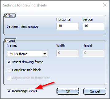
![]() Please note:
Please note:
If the changed settings add further views, these may have to be arranged manually.
Sectional views of sheet metal parts
From HiCAD 2020 SP2 onwards, the viewing direction of the sectional views of sheet metal parts in the workshop drawing is to the right or downwards. Aligned cuts are accordingly to the right or below.
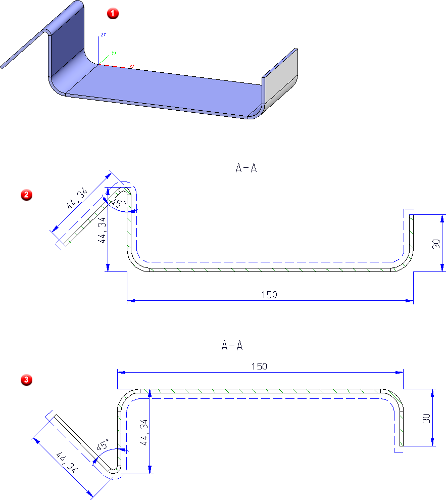
(1) 3-D model in axonometry, (2) sectional view in workshop drawing before HiCAD 2020 SP1, (3) sectional view in workshop drawing from HiCAD 2020 SP1 onwards
Please note that updating your existing drawings can change the position of the sections.
Dimensioning of sheet metal parts
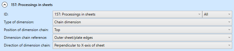
In the configuration for the usage "Sheets" DEFAULT(KANTBLECHE), Dimensioning rule 157: Processings in sheets is now additionally preset for the front view and the top view as follows:
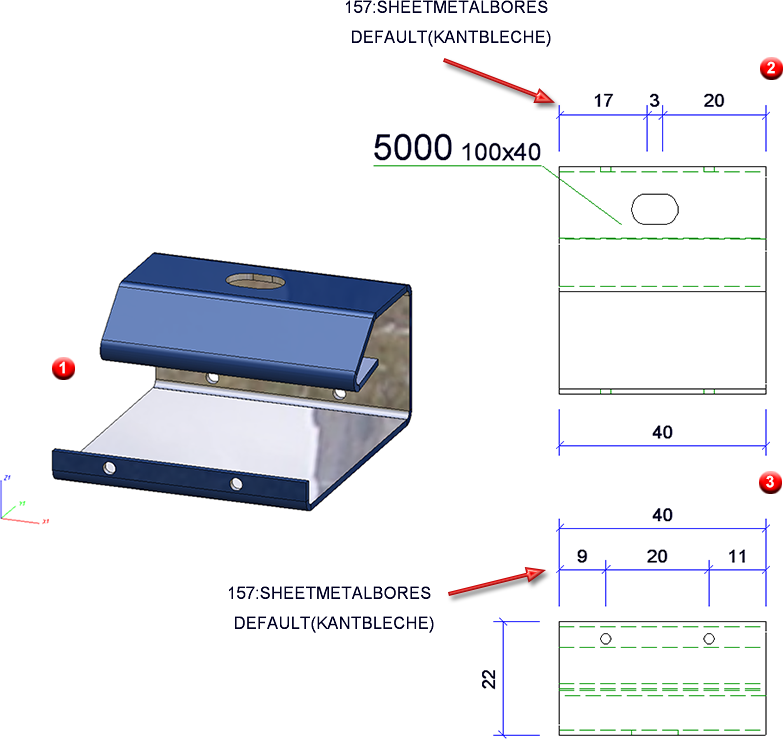
(1) 3-D model, (2) front view and (3) top view in workshop drawing
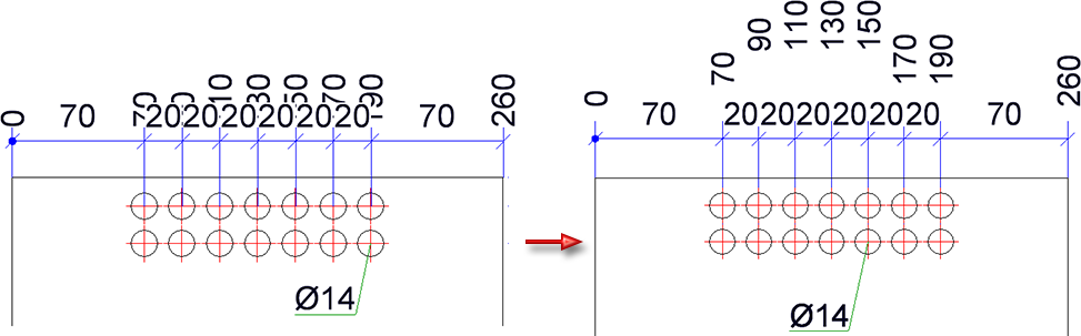
Optimisation of base points
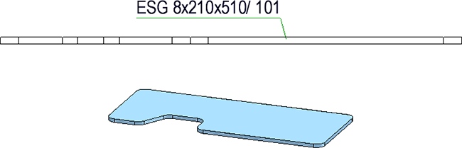
Since SP1, for automatically dimensioned developments of sheet metal parts, the (unshortened) projection lines are only drawn to the nearest point on the object to be dimensioned, i.e. to the next point on the contour. As of SP2 this also applies to sheet metal parts, steel engineering plates and glass panes.
Tangential transitions when dimensioning contours
The selection of base points has changed for the automatic dimensioning of contours. This change applies to applies to sheet metal parts, steel engineering plates and glass panes.
Until now, when dimensioning contours, the end points of the individual edges were dimensioned. However, this is usually not desired in practice. From SP2 onwards, the following base points are therefore taken into account when dimensioning contours:
Outer contours
-
Lines running perpendicular to the dimension line
- Extreme points of outer contours that lie in the dimensional direction (also points lying on an arc or freeform line)
- All points with a bend
Except for inverse curves, where the centre lies on both adjacent lines.
- Theoretical intersection points of curves in the outer contour
For each arc that is tangentially adjacent to a straight line on both sides, the theoretical intersection point of the two lines is dimensioned if the angle of the two lines is greater than 50 degrees (i.e. not for very acute angles only). When merging with other dimensions, theoretical intersections are removed first, which affects the length of the projection lines.
Bores/Subtractions
- Centres of circles, bores and slots
Depending on the setting specified at Drawing > Itemisation/Detailing > Dim...  > Dimensioning Settings
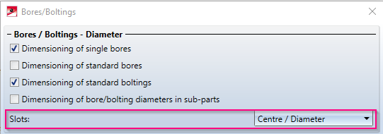
- Lines, points and theoretical intersection points as for outer contours
This change concerns the dimensioning rules for outer contours and bores/subtractions of sheet metal parts (and their developments), steel engineering plates and glass panes.
Dimensioning of outer contour, before HiCAD 2020 SP2
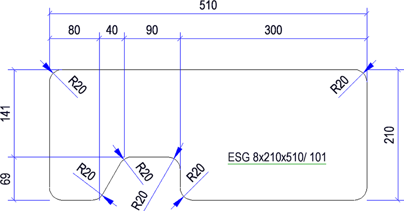
Dimensioning of outer contour with HiCAD 2020 SP2
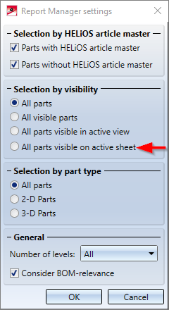
Bills of materials - All visible parts on active sheet
When creating BOMs, it is now possible to consider only the visible parts of the active sheet area. Therefore the settings for BOMs have been extended accordingly.
Insert part, via standard part catalogue
The function Drawing > Insert Part > Cat  has been enhanced. When HiCAD asks yout to determine tfitting poiint in the drawing, you can right-click to activate the displayed context menu:

Here you have the possibility to select another catalogue part, to take over the origin of the coordinate system as target point or to cancel the function.
The function remains active after the insertion of a catalogue part. You can install the selected catalogue part several times or reactivate the context menu shown above by pressing the right mouse button.
You end the function with the middle mouse button or with the Cancel function in the context menu.
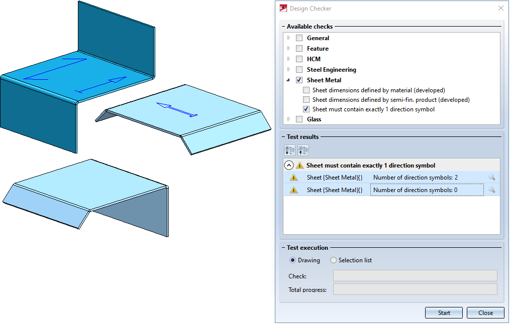
Design Checker - New check for sheet metal parts
The Design Checker offers a new check for sheet metal parts called Sheet must contain exactly 1 direction symbol. This check finds all sheet metal parts with no or more than one direction symbol.
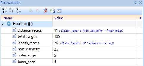
Nested variables and formulas
It is now possible to specify a formula that contains additional variables when defining the value of a variable. Especially with complex parts, the variable structure can become much clearer.
Thereby variables may be nested arbitrarily deeply into each other:
However no cyclic structures may occur (variable a refers to variable b, which refers to variable a), since these cannot be computed. In this case the automatic calculation of the formula values is no longer possible. The last values are retained and an error mark is displayed at the affected variables, which shows an explanatory tooltip when the cursor is moved over them:
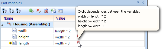
In this case, remove the cyclic dependency by editing the formulas to remove the error markings and reactivate the automatic calculation of the formula values.
Service Pack 1 2020 (V 2501)
Restore HiCAD GUI to default
If you want to reset the HiCAD user interface, for example because ICN windows are no longer displayed although they have been activated with Settings > Docking windows or because incorrect icons or texts are displayed in the HiCAD toolbars or ribbons, use the contains the tool
HiCADGUIReset.exe
tool in the HiCAD EXE directory. This tool resets the entire HiCAD user interface, i.e. all corresponding settings in the Windows Registry and in the %APPDATA% directory, to the state after a new HiCAD installation.
After starting the tool, the following dialogue window is displayed.
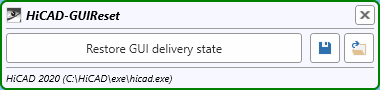
HiCAD should be closed before calling the tool. If this is not the case, a corresponding message is displayed:
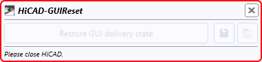
Then close HiCAD. HiCADGUIReset does not have to be closed before!
You start the reset by clicking the Restore GUI delivery state button. With the functions Save GUI settings  and Load GUI settings
  the current settings can be saved and reloaded at any time. The file format is hicadgui. This is also useful if you use HiCAD at different workstations, e.g. on a laptop and on a computer with two monitors. You can simply save the settings of both workstations and then load the respective settings file you need.
Before you start the reset you should always create a backup of your current settings.
 Please remember that after a restoring of the GUI to default, user-defined toolbars will be no longer available!
Itemisation
Switch to new standard itemisation
As of HiCAD 2020 SP1, you can use the Configuration Editor to define the procedure for starting the itemization in a model drawing that still uses the itemization up to HiCAD 2017. To do this, open the Configuration Editor and choose System settings > Itemisation > Switch to 'Standard itemisation used since HiCAD 2018'.
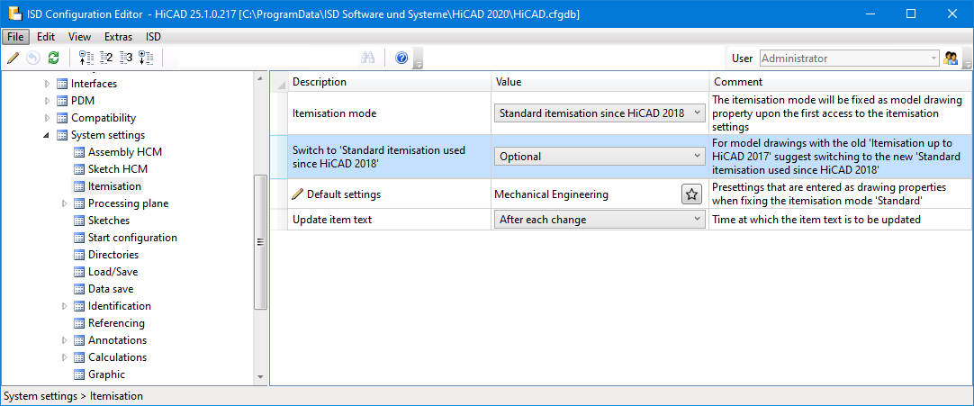
The following options are available here:
- Never
No message or query will be displayed. This means that the itemisation up to HiCAD 2017 will still be used. - Optional
A message will be displayed, informing you that the itemisation up to HiCAD 2017 will still be used.

You then have the option of determining whether or not the itemization should be converted to the standard itemization. To Cancel the itemization function, use the same named option.
- Mandatory
Here, too, the message will be displayed, informing you that the itemisation up to HiCAD 2017 will still be used.
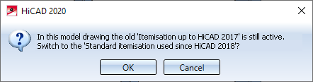
Here, however, you only have the possibility to switch to the standard itemisation with OK or to Cancel the itemization function.
The default setting is Optional.
Sheet Metal parts with visible side
Sheet Metal parts that have an visible side identifier assigned to them are included in the identical part search. For example, if the model drawing contains two Sheet Metal parts of the same size, one of which has an ID for the visible side identifier, then the sheets are not considered identical and will receive different item numbers.
Enhanced ICN
New ICN window for views
The ICN window for views has been completely revised and makes working with many views much easier. Model and sheet areas are now marked by new symbols. Like the parts structure, the view structure is now also displayed - optionally - in multiple columns. For each view an icon for the respective view type, the view name, an icon for the view mode and the scale of the view are displayed. Also new is the extended toolbar, which allows you to create and update sheet areas without having to activate a context menu first. The automatic sorting mode is also worth mentioning, which ensures that sheet views are sorted correctly according to their name. This mode can be switched on and off.
Also new is that certain views are marked with appropriate symbols. This applies to views that are hidden in the model drawing, views that have been "frozen", so-called "QuickViews", and sheet developments for which the synchronization was locked with the function Suppress sheet update in the context menu of sheet development.
|
|
The view is hidden in the model drawing. |
|
|
The view is "frozen", i.e. it is visible but cannot be edited. |
|
|
This symbol indicates sheet metal developments for which the adjustment was locked with the Suppress sheet update function in the context menu of the sheet metal development. |
|
|
This symbol indicates that the view is a QuickView . |


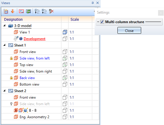
 If, for example, a view is a list view, a sectional view and also an exploded view at the same time, then several symbols will be displayed
Marking of sheet developments
Sheet developments for which updates were prevented with the Suppress update  function in the context menu of sheet development are now indicated in the ICN by the
  symbol.
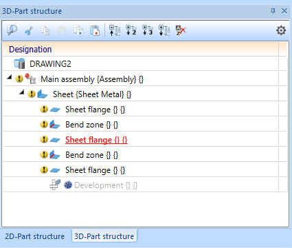
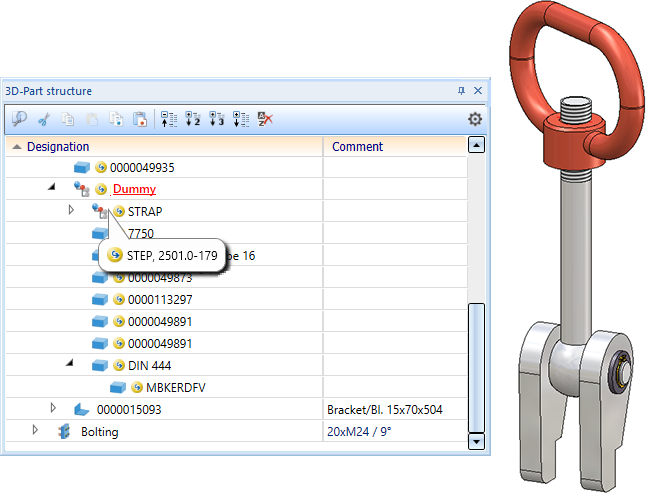
Marking of imported parts in the ICN
All parts that you insert into the model drawing using the 3-D Import function are marked with the  symbol in the ICN. If you place the cursor over the symbol, you will obtain further information on the relevant part, such as the imported file format and the HiCAD version with which the part was imported.
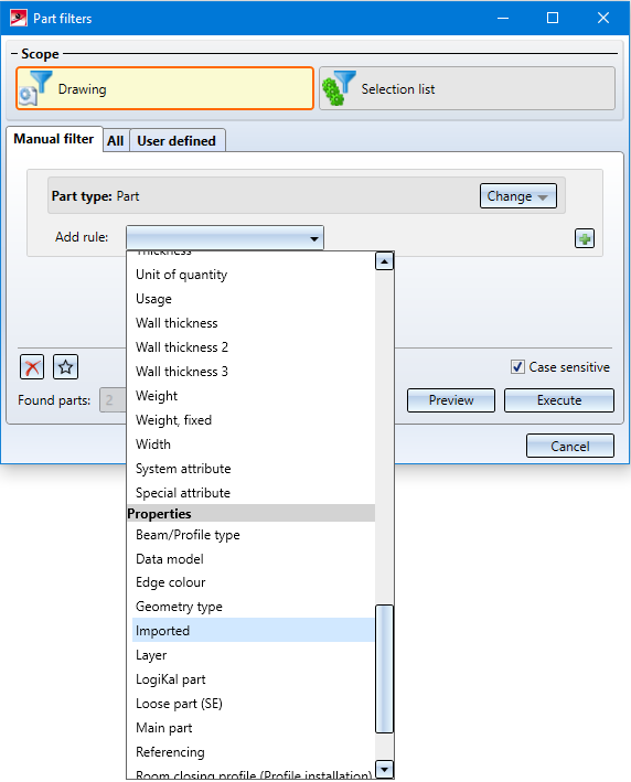
Part filters - Imported parts
With the 3-D Import function, parts inserted into the model drawing can also be searched with the Find  function in the transparent toolbar. The part filter dialogue has been extended accordingly.
Repeated paste from clipboard
Previously, pasting from the HiCAD clipboard was performed "in a loop", i.e. after pasting from the clipboard, the function remained active, so that you could paste the clipboard contents several times at different positions in the construction.
From HiCAD 2020 SP1 onwards, this behaviour can be defined in the Configuration Editor at System settings > Miscellaneous by activating / deactivating the Repeated paste from clipboard checkbox .
- If the checkbox is active, the Paste from HiCAD Clipboard function remains active after the first paste, so that you can insert the clipboard content several times at different positions in the model drawing. You end the function with the middle mouse button.
- If the checkbox is inactive, the Paste from HiCAD Clipboard function will be automatically ended after the first paste. This is the default setting for new installations as of SP1.
During an update installation, the previous behaviour remains unchanged, i.e. repeated pasting remains the default setting.
Derived drawings
Readability of running dimension chains
The creation of running chain dimensions has been improved by preventing dimension figure collisions.
AutoSave - Time interval per model drawing
As of HiCAD 2020 SP1, the time interval of the AutoSave mechanism per opened model drawing applies, i.e. HiCAD remembers the elapsed time of the current model drawing in the case of a drawing switch. For the model drawing that you switch to, the time interval runs from the first change to the model drawing or from a remaining time previously noted for this model drawing.
An example:
The time interval is set to 10 minutes and you are working with three model drawing times K1, K2 and K3.
|
Timer |
|
Time remaining |
|
[00:00] |
You have loaded K1 and for for 9 minutes in K1. |
K1 = 1 min. |
|
[09:00] |
You switch to an empty drawing thumbnail, load K2 and work on K2 for 11 minutes. |
|
|
[19:00] |
After 10 minutes the time interval for K2 has expired and an interim backup of K2 is created. |
K2 = 9 min. |
|
[20:00] |
You switch back to K1 and work on K1 for 4 minutes. |
|
|
[21:00] |
After 1 minute, an interim backup of K1 is created. |
|
|
[24:00] |
You switch to an empty drawing thumbnail, load K3 and work on K3 for 12 minutes. |
K1 = 7 min. |
|
[34:00] |
After 10 min. the interim backup of K3 takes place. |
|
|
[36:00] |
You switch to K2 and work on K2 for 13 minutes. |
K3 = 8 min. |
|
[45:00] |
After 9 min. K2 is backed up. |
|
|
[49:00] |
You switch to K1. |
K2 = 6 min. |
|
etc. |
|
|
Others
Delete parts
If parts of the model drawing are deleted via the context menu in the ICN or in the model drawing, the part that was active before the part was deleted is then active. If you delete the active part, the first part of the part structure is active.
The same applies to multiple selection. This means that when you delete a multiple selection, the part that was active before the multiple selection was deleted is then active. If the active part belongs to the deleted parts list, the first part of the parts structure is then active.
Coordinate System display
In the CS display toolbar, the symbol for part orientation has been changed: 
Major Release 2020 (V 2500)
|
New Mask Editor in HELiOS 2020 Due to a complete revision of the Mask Editor for HELiOS 2020 the previous mask format has been changed from .MSK to .XML. In addition, mask files are now managed outside the installation directory, resulting in some changes in the system architecture that administrators should urgently consider:
Please read the installation instructions before updating to HiCAD / HELiOS 2020. |
Licensing
- The new Extension Module HiCAD Point Cloud provides an associative solution for the integrated representation of point clouds in HiCAD. Besides the import of common point cloud formats, the imported point cloud can be placed and clipped in HiCAD. When drawing CAD geometries, you can also refer specifically to point information from the point cloud. A prerequisite for using the new module is either one of the Basic Modules HiCAD Creator or HiCAD Solution.
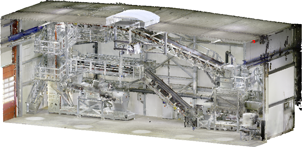
Example of a Point Cloud imported in HiCAD (Image: VHV Anlagenbau GmbH, Hörstel)
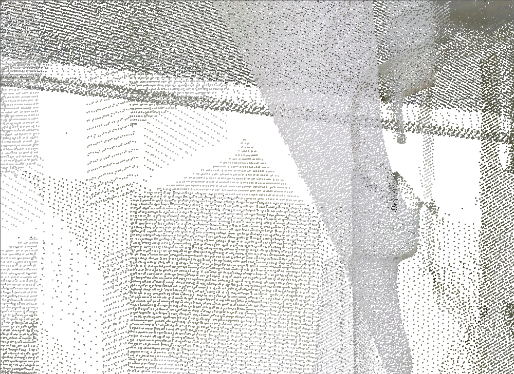
Highly enlarged section of the point cloud shown above
An example of a point cloud can be found here.
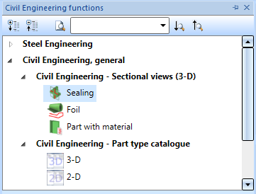
- The civil engineering functions (in the docking window under Civil Engineering General ) are now also available in the following extension modules:
- Sheet Metal Professional
- Beams
- Metal Engineering
- Steel Engineering
- Steel Engineering, Stairs + Railings
- Profile Installation
- Element Installation
- The basic module HiCAD Spooler now contains the same range of functions as HiCAD Solution, e.g. the functions for itemisation and drawing derivation. Furthermore, the module can be linked with the same extension modules as HiCAD Solution, for instance with the HiCAD Beams module.
Performance
- The HiCAD dimensioning functions are now much faster thanks to an internal change to saving by bodies.
- In large model drawings and assemblies, UNDO actions after cloning of assemblies can now be carried out much faster.
- With the release of HiCAD 2020, both the changing of item numbers and the updating of item number tags have been speeded up significantly.
AutoSave
The AutoSave function has been upgraded particularly in regard to the backup time:
- The automatic backup timer is enabled only after a drawing has been fully loaded and all updates have been completed.
-
When saving a drawing, the timer will be reset.
- The symbols are enlarged.
ISOCPEUR font
HiCAD 2020 supports the ISOCPEUR font, which is, for example, recommended by the Austrian Steel Engineering Association. If this font has been installed on your computer or network, it can be (like the Arial font) selected in the Parameter configuration dialogue window (ParKonfigComp.exe / ParKonfigUser.exe) as the default font. Otherwise, this font is greyed out in the dialogue window.
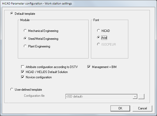
Please note:
The ISOCPEUR font is not part of HiCAD's scope of delivery and will therefore not be installed together with HiCAD.
![]() Important:
Important:
By running the parameter configuration, customer-specific settings, flags, drawing frames etc. are changed to settings predefined by ISD.
Enhanced ICN features
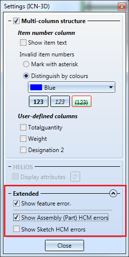
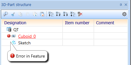
The Settings for the 3-D part structure allow to indicate parts with feature error or HCM constraints with error in the part structure.
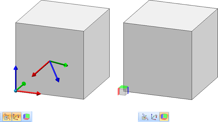
Switch on/off representation of Coordinate Systems
For a better use of coordinate systems, HiCAD 2020 and higher allows you to switch on and off the part and fitting coordinate system of the currently active part directly via the corresponding symbols at the bottom of the user interface. As an alternative, you can either use the F8 key for the part coordinate system or SHIFT + F8 for the fitting coordinate system.

When switched on, a plastic representation of the respective coordinate system is displayed.
The following graphic shows an example with the part and installation coordinate system switched on.
Furthermore, the orientation of a part, which you have defined with the Part orientation function in the context menu for parts or the profile orientation can be shown/hidden. To do so, click on the symbol
 Profile orientation or Alignment of active 3-D part, alternatively use the F6 key. This is only possible if the setting Switch on/off with F6 keyunder System settings > Visualisation > Show alignment of active 3-D part in drawing or System settings > Visualisation > Indicate orientation of active Steel Engineering beam in the Configuration Management has been activated.
Point options
Absolute Z-position (AZ)
Analogous to the point options AX und AY the point option (AZ) Absolute Z-position  is now available. This option determines a point by specifying its Z-coordinate and accepting the X- and Y-coordinates of the last point.
Point from Point Cloud (PW)
The option (PW) Point from Point Cloud is required for working with HiCAD Point Cloud module.
Directories
Quick Access for directory selection
As with the dialogue window for loading and saving of files, selected directories can now also be added to the Quick Access folder, e.g., for DXF export of Sheet Metal parts.
Improved designations of directories in HiCAD Settings
The designations of the HiCAD directories in the dialogue window of the function > Settings > Directories have been improved.

Update catalogues
In the Configuration Editor at System settings > Catalogue > Track catalogue changes you can now determine how to proceed in case of catalogue changes in HiCAD. The default setting is Do not track, that is, the catalogue data will be loaded only once when you start HiCAD. After this, HiCAD will no longer check whether newer data exist. The reason for this is that a check for up-to-dateness of catalogues in HiCAD can significantly deteriorate the performance in some situations.
As of HiCAD 2020, the new Reload function offers the option to update catalogues after applying changes to them without having to close HiCAD, and without having to put up with drops in performance due to repeated checks for up-to-dateness.
You find the new function at Settings > Catalogue.
Drawing derivation
Dimensioning rules
- In the basic settings for the Usage "Sheet Metal" in the Configuration Editor (Configuration DEFAULT(KANTBLECHE) the dimensions with the ID
- 135: Parametric linear dimensions of sheets (SHEETMETAL_PARA_DISTANCE) and
- 136: Parametric angular dimensions of sheets (SHEETMETAL_PARA_ANGLE)
have been removed from all views. As a result, die dimensioning rules of this configuration has changed (only applicable to new installation).
- In the settings for the Usages Assembly column and Assembly girder in the Configuration Editor (Configuration ASSEMBLY_COLUMN and ASSEMBLY_BEAM) the following dimensions have been removed from the Top view (only applicable to new installation):
- In the settings for the Usages Assembly column and Assembly girder in the Configuration Editor (Configuration ASSEMBLY_COLUMN and ASSEMBLY_BEAM) the following dimensions have been removed from the Front view(only applicable to new installation):

- For the dimensioning rules
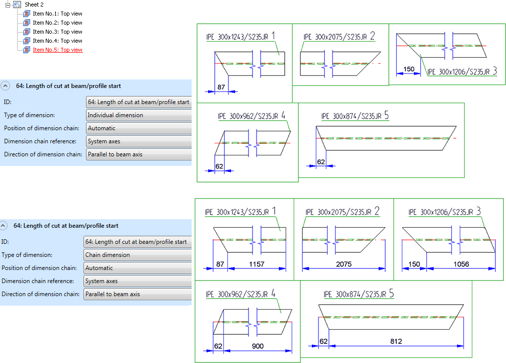
- 64: Length of cut at beam/profile start (SECTIONAL_ LENGTH_BEGIN) and
- 65: Length of cut at beam/profile end (SECTIONAL_ LENGTH_END)
the dimension type Individual dimension is now also permissible, in addition to the dimension type Chain dimension. If you choose Chain dimension as the dimension type, the chain of dimension will be lengthened according to the selected reference, and becomes a chain dimension. If you choose Individual dimension, only the length of the cut will be dimensioned. When updating model drawings from versions older than 2020, only the cut will be dimensioned, and no chain dimension will be created.
An example:
The image below shows a model drawing with cut beams.
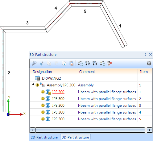
From this model drawing, a drawing was derived, considering only the beams and generating the top views:
Import of foreign formats
Insert 3-D foreign formats as parts in current model drawing
Data in the 3-D formats:
- STEP (*.stp, *.step)
- STL (*.stl) (the STL file must exist in the ASCII format!)
- IGES (*.igs, *.iges)
- VDAFS (*.vda)
- CATIAV4 and CATIAV5 (*.MDL, *.Model, *.EXp, *.ISO, *.DLV3, *.CATPart, *.CATProduct)
- ACIS (*.SAT)
- Parasolid (*.x_t, *.xmt_txt, *.x_b)
- ProE (*.prt)
- Unigraphics (*.prt)
- SOLIDWORKS (*.sldasm, *.sldprt)
- Inventor (*.ipt, *.iam)
- AutoCAD (*.dxf, *.dwg)
- JT (*.jt)
- PLMXML (*.plmxml)
- IFC (*.ifc, *.ifczip)
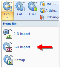
could previously only be imported to a new HiCAD drawing with the Drawing > New/Open > Open  > 3-D Import function. If you want to insert data in these formats to the current drawing, now choose the renamed function Drawing > Insert Parts > Exp. > 3-D Import.
The parts will then be inserted in the current drawing as an assembly with the name of the selected file.
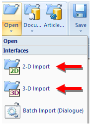
Import model drawings
When importing 2-D/3-D model drawings via interfaces, HiCAD 2020 distinguishes between 2-D and 3-D imports. For this purpose the old function Drawing > New/Open > Open > STEP, IGES, ... has been split into the 2 new functions called 2-D Import and 3-D Import.
HCM models in the Design Checker
The Design Checker now offers the following additional tests for HCM models.
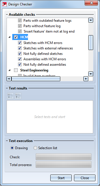
- Sketches with HCM errors
lists all sketches containing incorrect HCM references. - Sketches with external references
lists all sketches containing HCM constraints with external references. - Not fully defined sketches
lists all sketches that are not fully defined. - Assemblies with HCM errors
lists all assemblies containing incorrect references. - Not fully defined assemblies
lists all assemblies containing a HCM model that is not fully defined.
