Toolbars
At the bottom of the HiCAD user interface there are several toolbars available to
- preset the parameters for the representation of lines, surfaces and edges,
- switch on/off the visibility of coordinate systems, isolated points, dimensions etc. and
- determine the settings for the Autopilot.

Surface, line and edge parameters
These are:
- the surface colour (3-D model),
- the colour for lines and edges,
- the line type,
- the layer,
- combinations of colour, line type and layer.
To change one of the parameters, click the arrow next to the field in
question and choose the desired setting in the corresponding list box
![]() .
.
![]() Please note:
Please note:
- The settings you make here apply only temporarily, i.e. for the current HiCAD session.
- Once you start HiCAD, the parameters defined in the basic settings are displayed.
- The surface colour depends on the currently loaded material file.
- Click here for an overview of special layer numbers.
Visualisation
With the functions of this toolbar you can switch on or off the visibility of coordinate systems, isolated points, dimensions, HCM constraints etc. with one click. In certain situations - especially with large model drawings - this can make editing easier. For example, you can hide all dimensions of a model drawing without having to call a function in the context menu or ribbon first.
When visibility is switched on, the corresponding symbols are highlighted in colour.
|
|
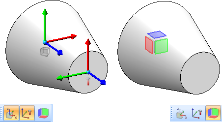
Toggle visibility of Part CS
Alternatively, you can also use the F8 key. The following figure shows an example with the display of the part and installation coordinate system and the part orientation switched on.
|
|
|
Toggle visibility of Fitting CS
With this switch the fitting coordinate system can be permanently shown/hidden. If the switch is active, the corresponding fitting coordinate system (if defined) is immediately displayed in a spatial representation each time a part is selected. Alternatively you can use SHIFT+F8 on the keyboard. |
|
|
Toggle visibility of beam orientation or drawing orientation of active 3-D part This button is used to show/hide the alignment of a beam/profile or the alignment of a part, which you have defined with the Part orientation function in the context menu for parts. Alternatively, you can also use the F6 key. |
|
|
Toggle visibility of isolated points (Drawing) All isolated points of the model drawing can be shown or hidden with one mouse click. |
|
|
Toggle visibility of dimensions (Drawing) All 2-D and 3-D dimensions of the model drawing can be shown or hidden with one mouse click. This applies both to drawing dimensions and parametric dimensions. |
|
|
Toggle visibility of dimensions (3-D Part HCM) |
|
|
Toggle visibility of constraints (3-D Part HCM) |
|
|
Toggle visibility of degrees of freedom (3-D C-Edge HCM) |
|
|
Toggle visibility of dimensions (3-D C-Edge HCM) |
|
|
Toggle visibility of constraints (3-D C-Edge HCM) |


 The toolbar with the functions for switching on/off coordinate systems can be found at
  Settings > Toolbars.
Autopilot Settings
The HiCAD Autopilot is a tool for determining points. If you move the cursor over the design objects with the autopilot switched on, information about snap points (snap symbols) and, in the case of various functions, also about lines, dimensions or texts is displayed. Whenever HiCAD requests a point determination, these snappable points can be taken over directly without having to activate a point option.
In the Autopilot Settings toolbar at the bottom of the HiCAD GUI the possible snap points are highlighted in colour.

Using this bar you can control which point options should be visible on the Autopilot by activating / deactivating the icons.
Detailed information about the Autopilot can be found here.
