Design Checker
Information > 3-D, Further > Design Checker 
The Design Checker is a tool that enables you to increase the quality of your drawings and reduce costs and time through an early detection of errors in the design. You can auto-check your drawings for their compliance with specific construction guidelines; it detects, for example, invalid features, incorrect bolting sets, dummy parts, and much more. If any errors are detected, HiCAD issues an appropriate message and suggests corrections.
A number of tests that cannot be modified has been predefined by the ISD. However, administrators or users with programming skills can define their Individual checks and use them in the Design Checker.
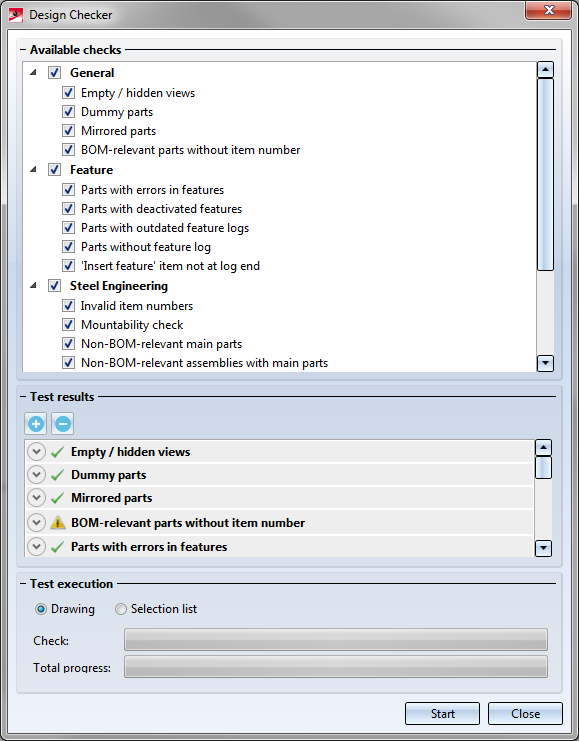
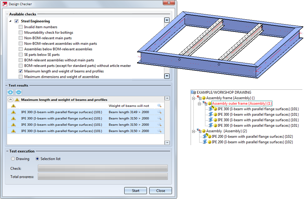
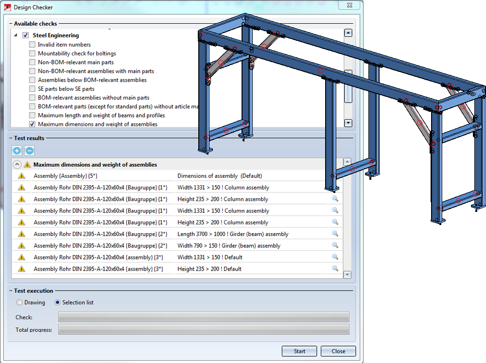
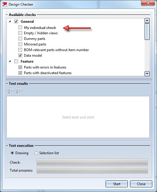
When you call the function, the Design Checker dialogue window will be displayed:
HiCAD checks the active drawing or all assemblies of the selection list. Activate the desired option in the Test execution area. As long as the dialogue window is open, you can freely change the selection list to be checked.
|
Start |
Use this button to start the check. All checks specified in the Available checks field. |
|
Stop |
This symbol replaces the start symbol while the check is being performed. If you click on the symbol, the check will be cancelled. |
|
Close |
Use this button to close the dialogue window. |
Select the checks that you want to perform and click the Start button to execute the checks. The current state of the check is indicated by the Test and Total progress bars in the dialogue, separately for the currently performed check and the total progress for all checks.
The results of the checks will be shown in the Test results pane.
The symbols have the following meaning:
|
|
No errors or warnings have been detected. |
|
|
Errors or warnings have been detected. |
|
|
The check could not be performed (e.g. if the script belonging to the check was faulty, or if the drawing contains assemblies to which the check could not be applied). |

Click the  symbol to obtain more detailed information on the test results. To expand or collapse all test results, click
  or
or  , respectively.
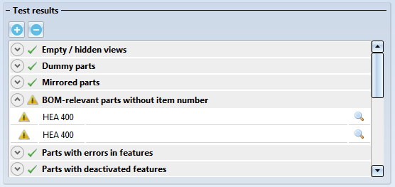
The symbols within a test result have the following meaning:

|
An error has been detected / warning. |

|
No errors have been detected. |
When you click on a result list item, the corresponding part will be highlighted in your drawing. A multiple selection of parts (press CTRL+click) is also possible. The highlighting will still be preserved if you move or rotate the view while the Design Checker is open.
Click the  symbol to zoom in on the part causing the error.
 Please note:
- When the dialogue box of the Design Checker is opened, you can optionally do edits of the construction, for example recalculate feature, show and hide parts, fix parts, delete parts etc.
- You can find further functions under
 in the menu Data structure.
The checks need to be based on the HiCAD .NET API and must be provided as C# or Python scripts. User-specific checks should only be defined by administrators or users with sound knowledge of the HiCAD API and Python script creation. The availability of checks in the Design Checker as well as the configuration of the tree structure of the checks can be specified in the DesignChecks.XML file in the HiCAD folder Script.
Different checks have been predefined by ISD:
- General checks
- Feature checks
- Steel Engineering checks
- Sheet Metal checks and
- Glass checks

General checks
- Empty/hidden views
- Dummy parts (parts without geometry)
- Mirrored parts
- BOM-relevant pats without item number
- Data model
Feature checks
- Parts with errors in features
- Parts with deactivated features
- Parts with outdated feature logs
- Parts without feature log
- Parts with 'Insert feature' item not at log end
HCM checks
- Sketches with HCM errors
- Sketches with external references
- Not fully defined sketches
- Assemblies with HCM errors
- Not fully defined assemblies
Steel Engineering checks
- Invalid item numbers
- Mountability check for boltings
Here it is checked whether screws or bolts can be inserted/pulled out without collisions and whether an appropriate tool for bolts and nuts will have enough space. If these criteria apply, the mountability check will be successful.


- Non-BOM-relevant main parts
Checks the BOM-relevance of assembly main parts - Non-BOM-relevant assemblies with main parts
Checks the BOM-relevance of assemblies with an assembly main part - Assemblies below BOM-relevant assemblies
Checks whether BOM-relevant assemblies contain other BOM-relevant assemblies - SE part below SE part
Checks whether other BOM-relevant parts have been assigned to BOM-relevant parts - BOM-relevant assemblies without main parts
Checks whether BOM-relevant assemblies without main part exist - BOM-relevant parts (except for standard parts) without article master
Checks which part(s) of the model drawing are BOM-relevant, but have no article master. Standard parts (incl. standard beams and profiles) will not be considered in the process. - Maximum length and weight of beams and profiles
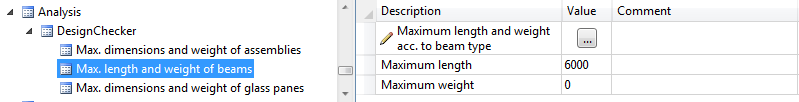
Checks whether your drawing contains beams or profiles the length or weight of which exceeds the maximum values specified in the Configuration Editor, at Analysis > DesignChecker. For comparison with the maximum length, the actual beam length and the part attribute Weight (§01) of the beam will be used. The units of measurement specified in HiCAD will apply, i.e. normally mm and kg.
If no maximum values >0 have been specified in the Configuration Editor, the calculation cannot be performed. In this case the Design Checker will issue an appropriate message.
The check can also be done depending on the beam types (catalog designation). The parameter Maximal length and weight of beams serves for this. By clicking the symbol  a dialogue box appears, in which you can type in the maximal values of the beam/profile type as desired.
The profile type can be chosen by clicking in the catalogue.
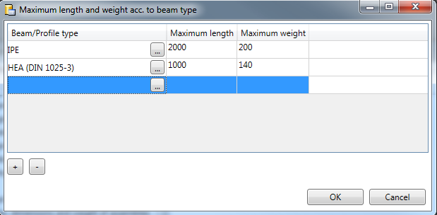
A new row resp. the current row can be deleted with the buttons  or
or  .
.
- Maximum dimensions and weight of assemblies
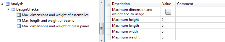
Checks whether your drawing contains assemblies the dimensions or weight of which exceeds the maximum values specified in the Configuration Editor, at Analysis > DesignChecker. For comparison with the maximum values, the part attributes Length (§03), Width (§02), Height (§04) , and Weight (§01) of the beam will be used.
For this test the following requirements must be met:
- The assemblies must have an assembly main part. The calculation of the length, width and height is based on this main part (to be more precise, on the coordinate system of this part). For example, if you want to check whether an assembly will have enough space on the loading area of a truck, (with the loading area specified by maximum values), the direction for the length will also be the direction in which the assembly is loaded onto the truck. This means that the Design Checker will not check whether an assembly exceeding the maximum values will still have enough space on the loading area of the truck if it (the assembly) is rotated.
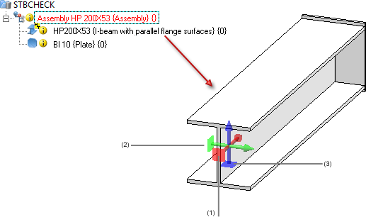
(1) X-direction: Length, (2) Y-direction: Width, (3) Z-direction: Height
- In the Configuration Editor, at Analysis > DesignChecker > Max. dimensions and weight of assemblies the maximum values need to be > 0. Please note that the values will be in the unit of measurement specified in HiCAD (normally mm and kg). If no maximum values have been specified, the Design Checker will issue an appropriate message.
The check can also be done depending on the beam types (catalog designation). The parameter Maximal length and weight of beams serves for this. By clicking the symbol a dialogue box appears, in which you can type in the maximal values of the beam/profile type as desired.
The profile type can be chosen by clicking in the catalogue.
A new row resp. the current row can be deleted with the buttons or .
- The entry Update immediatelyshould be chosen in the configuration management at Modelling > Part properties> Update part dimensions . Otherwise the Design Checker delivers an appropriate message.
- Furthermore, the entry Always should be chosen at Modelling > Part properties> Weight calculation.
 If you change the settings at Modelling > Part properties, please restart HiCAD.
Sheet Metal
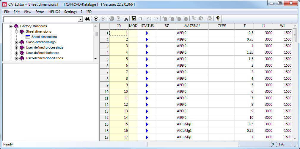
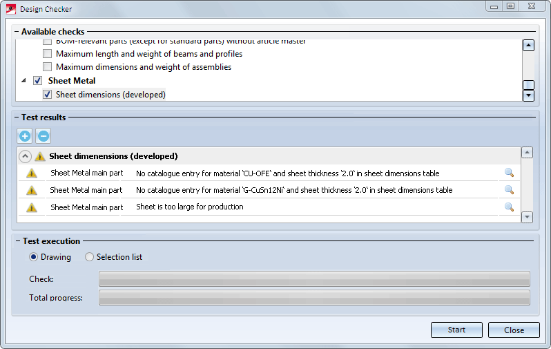
- Sheet dimensions developed
The check Sheet dimensions developed checks whether the blank sizes of sheet developments exceed the maximum dimensions according to the sheet dimensioning table in the Catalogue Editor (Factory standards > Sheet dimensions). If this is the case, the sheet cannot be produced. The sheet dimensioning table in the Catalogue Editor consists the practice-oriented dimensions (Column L1 and W1) for the corresponding materials and sheet thickness (Column T).
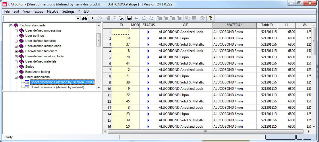
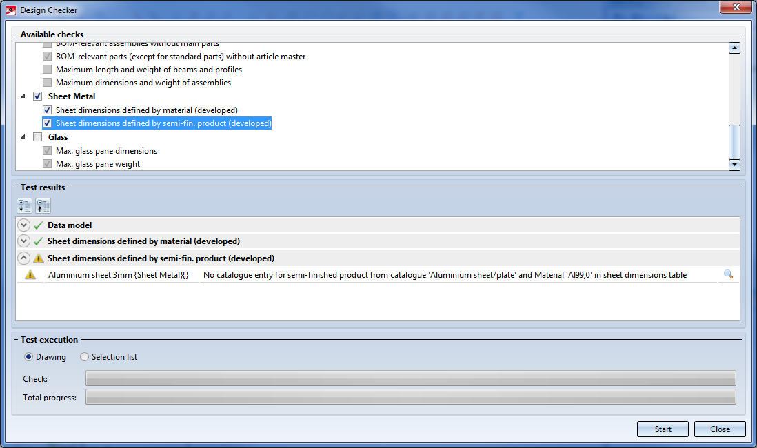
- Sheet dimensions defined by semi-fin. prod. (developed)
This check checks the dimensioning for semi-finished products. For this, the table Sheet dimensions (defined by semi-fin. prod.) under Factory Standards> Sheet dimensions is evaluated in the CATeditor. The table shows the maximum length and width of the semi-finished product as a function of the TableID of the semi-finished product.
The dimensions of the ALUCOBOND panels stored in this table are predefined by ISD. However, you can extend this table as required for other semi-finished products.
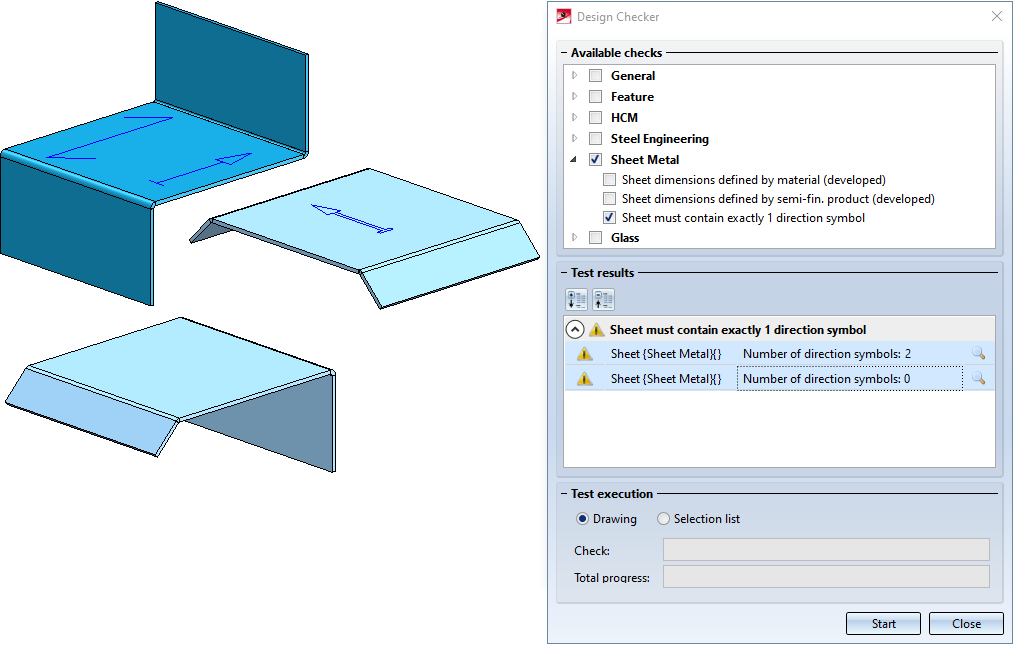
- Sheet must contain exactly 1 direction symbol
This check finds all sheet metal parts with no or more than one direction symbol.
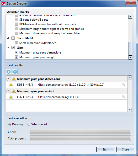
Glass
With the checks
Maximal dimensions
Maximal weight of glass panes.
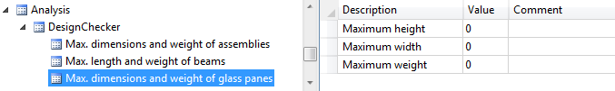
it is checked whether the dimensions and weights of glass panes exceed the maximum values specified in the Configuration Editor, at Analysis > DesignChecker > Max. dimensions and weight of glass panes
Individual checks
Administrators or users with programming experience can define their own checks and integrate them into Design Checker.
These checks are required to meet the following conditions:
- The checks use HiCAD .NET API.
- The checks are written in C# or Python. This is the same technique used for the rules and constraints in HiCAD design variants.
Suppose you have created such a Python script for an individual check and it has the name DC_USER.PY. To integrate the test into the Design Checker, proceed as follows:
- make a copy of the script in the HiCAD folder Script/DesignChecker.
- All checks offered by Design Checker are specified in DesignChecks.xml In order to make the new check accessible in Design Checker, all xml files must be extended accordingly. For this, you should consider to assign your check to a group where it is to be offered. Folllowing groups are predefined by ISD:
- General
- Feature
- Steel Engineering
- Sheet Metal
- Glass
In the file DesignChecks.xml, one block belongs to each of these groups as follows
|
|
<DesignCheckGroup ....> |
Beginning of group |
|
|
<DesignCheckDescription ...... /> |
Check |
|
|
<DesignCheckDescription ...... /> |
Check |
|
|
</DesignCheckGroup> |
End of group |
For example, if you want to add your test to the General group, you must add the following line:
<DesignCheckDescription DesignCheckId="DC_User" DesignationTextKey="" DesignationText="My test" ExecuteCheck="True" DescriptionText="My individual test" Script="DC_User.py" />
The ExecuteCheck parameter determines whether the check is active when the Design Checker is called. The parameter DesignationText den Text, der für diesen Test im Design Checker angezeigt wird.
<DesignCheckGroup DesignationTextKey="DC_TestsGeneral" DesignationText="Allgemein" ExecuteCheck="True">
<DesignCheckDescription DesignCheckId="DC_User" DesignationTextKey="" DesignationText="My test" ExecuteCheck="True" DescriptionText="" Script="DC_User.py" />
<DesignCheckDescription DesignCheckId="TestEmptyOrInvisibleViews" DesignationTextKey="DC_TestEmptyOrInvisibleViews" DesignationText="Empty /hidden views" ExecuteCheck="False" DescriptionText="" Script="DC_Views.py" />
<DesignCheckDescription DesignCheckId="TestEmptyParts" DesignationTextKey="DC_TestEmptyParts" DesignationText="Dummy parts" ExecuteCheck="False" DescriptionText="" Script="DC_EmptyParts.py" />
<DesignCheckDescription DesignCheckId="TestMiroredParts" DesignationTextKey="DC_TestMiroredParts" DesignationText="Mirrored parts" ExecuteCheck="False" DescriptionText="" Script="DC_MirroredParts.py" />
<DesignCheckDescription DesignCheckId="PartsNoItemNumbers" DesignationTextKey="DC_PartsNoItemNumbers" DesignationText="BOM relevant parts without item number" ExecuteCheck="False" DescriptionText="" Script="DC_PartsNoItemNumbers.py" />
<DesignCheckDescription DesignCheckId="BuildCadModel" DesignationTextKey="DataModel" DesignationText="Data model" ExecuteCheck="True" DescriptionText="" Script="DC_BuildCadModel.py">
<RepairScripts>
<RepairScript RepairScriptId="FixCadStructure" />
</RepairScripts>
</DesignCheckDescription>
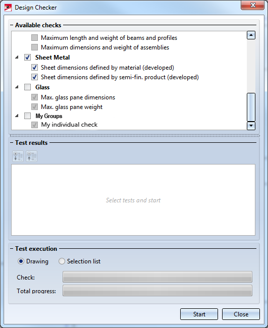
Result:
If your tests are to be listed in a separate group, you must create a corresponding DesignCheckGroup, for example
<DesignCheckGroup DesignationTextKey="" DesignationText="My groups" ExecuteCheck="False">
<DesignCheckDescription DesignCheckId="DC_User" DesignationTextKey="" DesignationText="My individual check" ExecuteCheck="True" DescriptionText="" Script="DC_User.py" />
</DesignCheckGroup>
Result:

Information - Other Functions • Information - Data Structure Check