3-D - What's New?

Service Pack 2 2020 (V 2502)
Model and process parts
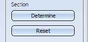
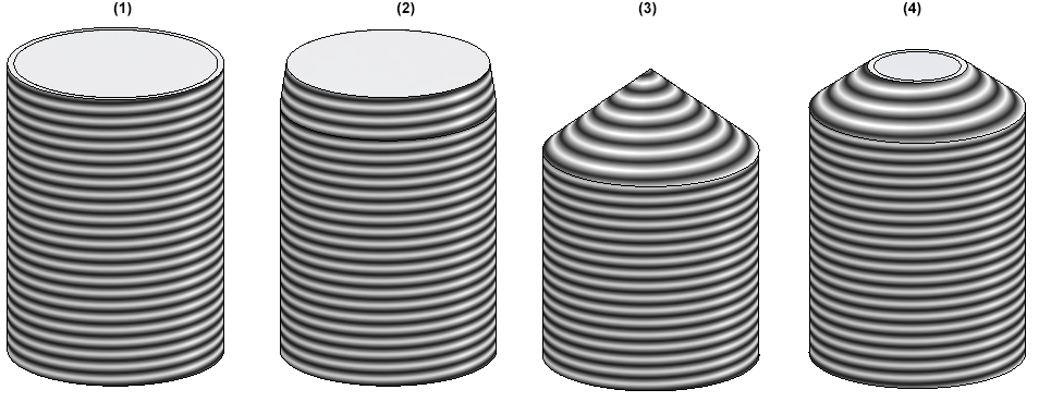
Internal/external thread with runout
In the Internal/external thread  function, thread runouts are now also possible.
The following options are available for runout length determination :
- Value, as part of thread length
The runout has the length specified in the Value field. The specified thread length is shortened accordingly.
- Value, in addition to thread length
This is only possible with the length options Fixed length and To point. The specified value determines the length of the runout, the thread length does not change. If the sum of thread length and runout length is greater than the possible full thread length, the runout is automatically shortened. - Pitch factor, as part of thread length
The specified factor is multiplied by the thread pitch. The result is the runout length. The specified thread length is shortened accordingly. - Pitch factor, in addition to thread length
This is only possible with the length options Fixed length and To point. The specified factor is multiplied by the thread pitch. The result is the runout length, the thread length does not change. If the sum of thread length and runout length is greater than the possible full thread length, the runout is automatically shortened.
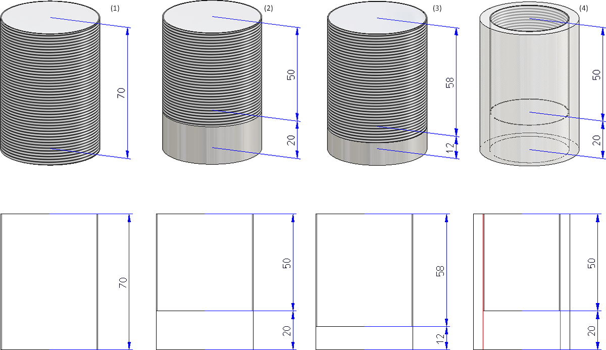
(1) Thread DIN 13 -M50x1.5, (2) Runout length 20, (3) Runout factor 8, (4) Internal thread DIN 40x1.5 with runout
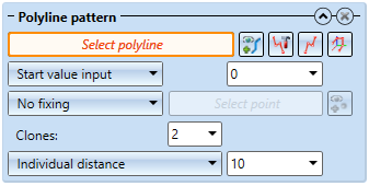
Changed dialogue for Clone parts (parametric) function
For the Clone > Param.  function, the sketch selection dialogue for linear patterns has changed slightly. The Process sketch
 , New sketch in plane
  and New 3-D sketch
  functions can now be activated directly in the top level of the dialogue.
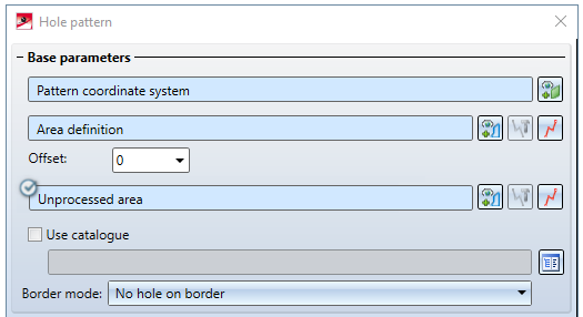
Similarly, the dialogue for the Hole pattern  function has been modified for the area definition and the unprocessed area.
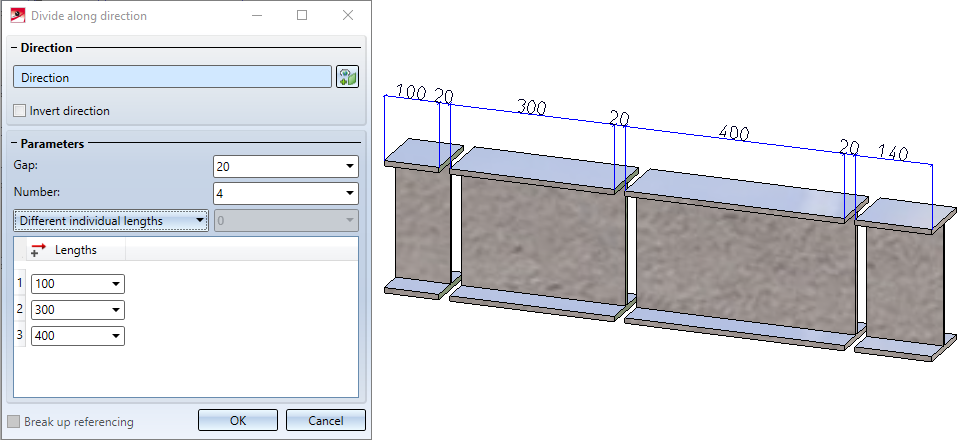
Divide along direction
The new Divide along direction  function at 3-D Standard > Process > Trim
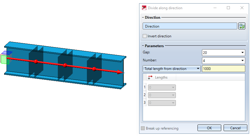
  > ... allows you to divide parts of the type Solid into several sections along one direction. Different division options are available, for example, the individual parts can have different lengths. In addition, a corresponding feature is created with this function so that the division can also be edited later.
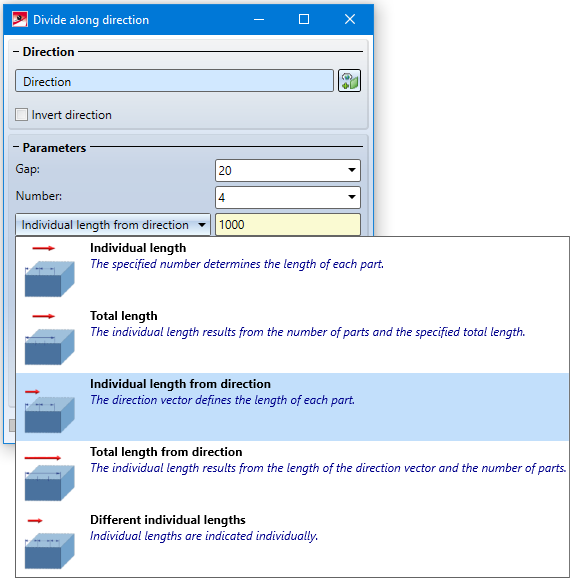
The direction, each division point and each gap are visualized in the drawing.
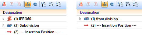
Each part is a separate part in the part structure - on the same hierarchy level as the initial part and with the same name. The initial part is assigned a feature with the name Subdivision, all other parts are assigned a feature with the name from division. The division can be edited by double-clicking on one of the features. All parts are adjusted accordingly.
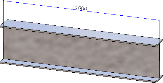
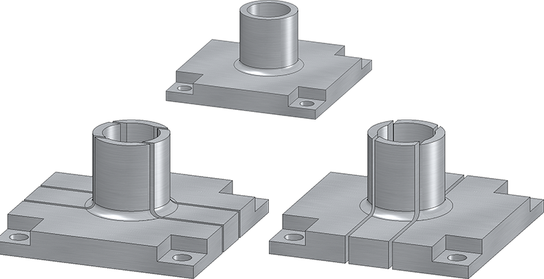
Example: Dividing a beam
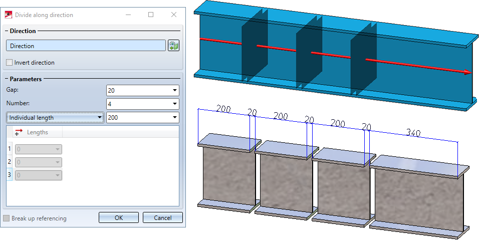
Example: Divided 3-D part
The function can also be found at Steel Engineering > Lengthen > Divide.
If you make changes to the initial part on features coming before the Subdivision feature, only the initial part will be recalculated. The division is performed at the same position relative to the part coordinate system. This means that neither the division points nor the parts are recalculated. If you want to adapt all sections to the changes, use the Update function in the feature context menu of the division.
Views
Detail view Cuboid/Sphere - New dialogue window and change options
The previous functions "Detail view Cuboid" and "Detail view Sphere" have been combined to form the new function Detail view Cuboid/Sphere  . You can switch between both modes in the Detail view dialogue window..
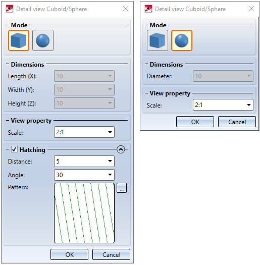
The new dialogue is much more user-friendly. For example, the cuboid and sphere are now visualized in the preview and can be drawn dynamically with the cursor.
From SP2 on it is also possible to change a Detail view Cuboid / Sphere subsequently. To do this, select the Change detail view  function in the Views Ribbon or in the context menu for views. Afterwards the corresponding dialogue window is displayed.
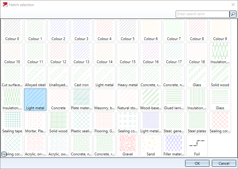
New dialogue window for hatching selection
The selection of hatch patterns in view functions has been revised. This affects the following functions:
- New sectional view
- Change sectional view
- Create detail view
- Change detail view
- New cut-out
- Change cut-out
- Hatching in sectional view and cut-out
The Hatch selection dialogue is now displayed for selecting the hatch pattern. If you point the cursor on one of the patterns, more information about the hatch pattern is displayed. By clicking on the magnifying glass symbol in the lower left corner you can also zoom the display of the patterns.
If the Cut surface hatching parameter is set to According to material, the hatching selection in the dialogues has no effect.
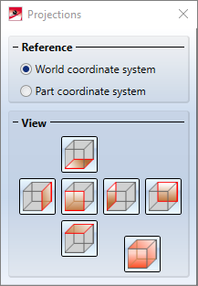
New dialogue window when creating views
The dialogue for selecting the projection when creating a new view has been replaced in SP2.
This concerns the following functions:


 Views > New > List > List from ref. view
 Views > New > List > Active part list
View properties of assemblies in context menu
As for other 3-D parts, the Properties in view area is now also available for assemblies in the context menu for assemblies beneath Properties.
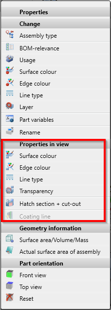
These functions allow you to define how the assembly is displayed in the active view.
Change representation in multiple views
If several views are selected in the ICN, the representation of all selected views can be changed in one step.
Note the following:
- The progress bar is view-comprehensive. This also applies to aborting hidden line calculations with the ESC key. Views that have not yet been calculated are then displayed in QuickView.
- If the display function is called with the CTRL key pressed, the views are always switched to exact representation. This also applies when the automatic QuickView is active.
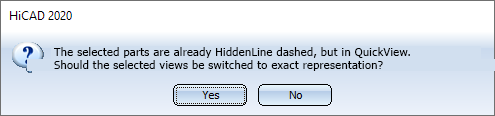
- If several views are selected, all of which already have the desired display, but are in QuickView, HiCAD asks whether the views should be switched to exact representation.
Hide parts in multiple views
Parts can now be hidden in all currently selected views in one step. To do this, you first select all required views in the ICN. Then select the parts to be hidden in the ICN or in model drawing and choose Part list, Hide in active view from the context menu (right-click). The parts are then hidden in all views that are selected in the ICN.
Standard parts / Standard processings
Grip lengths for rivet insertion
When inserting rivets, the grip length range of a sub-type is now also displayed. For this purpose, the tables for rivets in the catalogue at Fasteners > Rivets and at Factory standards > User-defined fasteners > User-defined rivets have been extended by the minimum (SMIN) and maximum (SMAX) grip length.
When rivets are installed, these values are displayed in the selection window. If a sub-type is selected, the dialogue window Grip length is preset with the value SMAX of the selected sub-type. This value can be changed, but must not be less than SMIN and not greater than SMAX.

 For update installations the grip length will not be displayed.
Change standard processings
Standard processings, which you create with the functions at 3-D Standard > Standard Processings, can also be edited from SP2 onwards by double-clicking on the corresponding entry in the feature log. This applies to all standard processings for which a catalogue selection is possible as well as through holes and letterings.
Sketches
Enhanced HiCAD VI / AV module
With the HiCAD VI / AV viewer solution, HiCAD constructions and drawings from third-party systems can be visualised. Furthermore, the module supports the plot generation/output and data export. In order to support the creation and editing of sketches for sectional and detailed views, the corresponding functions are now available on the Sketch Ribbon tab of the module.
Highlighting isolated points
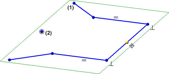
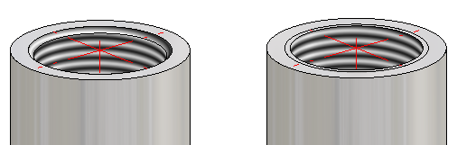
If the Enter constraints checkbox is active in the HCM settings for sketches or if a sketch is parameterized manually, the sketch points are highlighted in colour. As of SP2, this also applies to isolated points in a sketch. Start and end points of sketch lines are marked by a filled circle (1), isolated points of the sketch by a filled circle with a ring (2). This applies to planar sketches and 3-D sketches.
You define the size and colour of the highlighting in Configuration Editor at System settings > Sketch HCM.
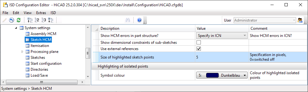
If sketch points are not to be highlighted, set the parameter Size of highlighted sketch points to 0.
Parameterized sketches in sectional views
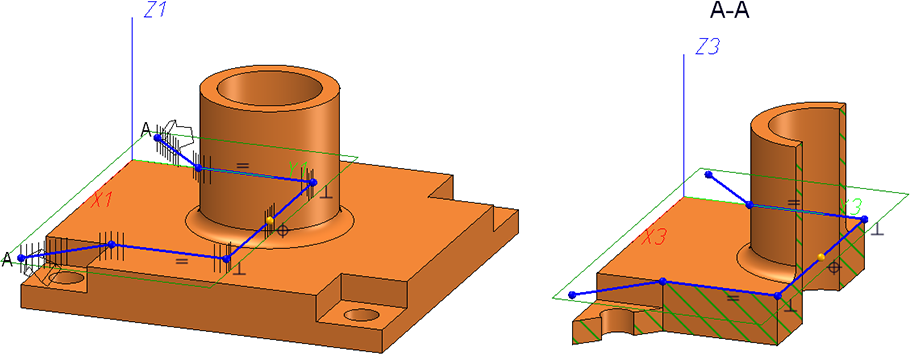
If a parameterized sketch with the purpose Create/Edit is active in a sectional view, the line end points of the sketch and the degrees of freedom are also visualized there.
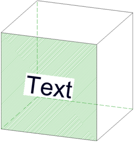
Size of sketch plane
HiCAD places a green frame around the geometry of a sketch, representing the plane of the sketch and completely enclosing the geometry of the sketch. From HiCAD 2020 SP2 onwards, HCM positional and dimensional constraints of the sketch are also taken into account.
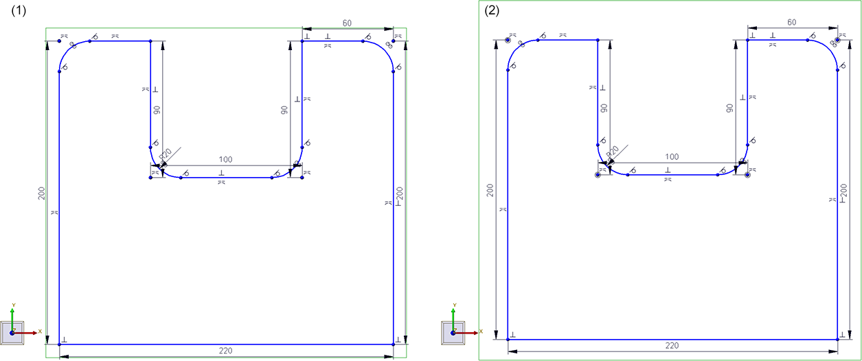
(1) before HiCAD 2020 SP2, (2) as of HiCAD 2020 SP2
3-D sketching tool - Changed arc creation
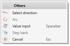
When inserting arcs, the arc radius and the opening angle are displayed at the cursor from SP2 onwards. If you want to use a specific radius, press the space bar or select the Value input function and enter the arc radius. You can determine the end point of the arc either by moving the cursor or with a point option.
First select the radius of the arc. To do this, drag the arc so that the desired radius is displayed and drop the cursor. The direction in which the arc is drawn (tangential or non-tangential) depends on the click point when the function is selected.
If you want to use a specific radius, press the space bar or select the function Value input and enter the arc radius.
You determine the end point of the arc either by placing the cursor (the opening angle is displayed) or with a point option.
If the last determined point is selected again, the drawing of an arc is automatically started.
If you specify a direction, the arc is drawn in the plane that is spanned by the specified direction and the tangent of the last edge at the connecting point.
Extended point options of the Autopilot
The point options
- Tangential point (T)
- Online through point (O)
- Theoretical intersection point (S2)
- Perpendicular base point (F)
offered by the Autopilot are also available for plane sketches and 3-D sketches. The option F is only displayed if several points have to be selected within a function, for example when selecting a direction. In addition, the following restrictions must be observed depending on the situation:
Planar sketches
|
|
T |
F |
O |
S2 |
|---|---|---|---|---|
|
|
|
|
|
|
|
|
|
|
|
|
|
|
|
|
|
 -
-
3-D sketches
|
|
T |
F |
O |
S2 |
|---|---|---|---|---|
|
|
|
|
|
|
|
|
|
|
|
|
|
|
|
|
|
Direction/Axis
When choosing a direction/axis over two points, T, F, O and S2 are offered at the second point, but not at the first point. This affects the following Sketch functions:
- Sketch > Draw > Freehand
> Transition curve - Sketch > Draw > Freehand
- Sketch > Derive > Take O... > Directed
- Sketch > Transform > Move
- Sketch > Transform > Rotate
- Sketch > Transform > Rotate > Move+Rotate
- Sketch > Transform > Mirror
- Sketch > Transform > Scale
- Sketch > Clone > Move
- Sketch > Clone > Rotate
- Sketch > Clone > Rotate > Move+Rotate
- Sketch > Clone > Mirror
- Sketch > Clone > Scale
C-edge HCM
Here S and S2 are offered for all functions, except for dragging.
Service Pack 1 2020 (V 2501)
Sketches
Enhanced 3-D sketching tool
With SP1 the 3-D sketching tool has been significantly enhanced. The dialogue window and the context menu have changed as well:
- The "Direction+ Distance" sketching mode is no longer available. Instead, you now use the Select direction function in the context menu to change the direction.
- If you want to enter a distance, length or radius using the keyboard, you can now also use the Value input function of the context menu instead of the space bar.
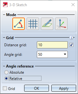
- If you activate the checkbox next to the Distance grid field in the dialogue window, the value for the distance grid is automatically adjusted when you zoom the drawing. This is the ISD default setting.
- The display of distances and angles during sketching has been improved.
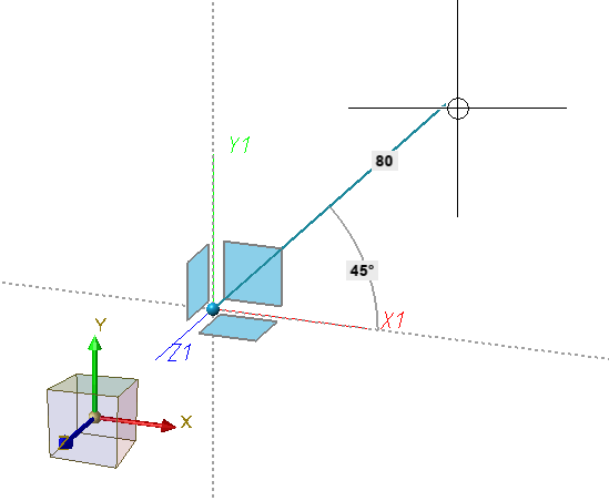
- By activating the Grid checkbox, grid lines and points can be displayed as tools for determining angles and distances, e.g.
- If a polyline is continued, it is also possible to draw an arc directly.
- When selecting the starting point, the autopilot also offers the point option O Online on edge and when determining the following points, both O and F Perpendicular base point. This depends on the cursor position.
- Connecting points of Plant Engineering parts are given special consideration during sketching. If the first point is a connecting point, then this point is used to define a grid direction. This means that the following lines are drawn in this direction.
More point options of the Autopilot during sketching
For both planar sketches and 3-D sketches, point options
 (O) Online to edge through point as well as
 (F) Perpendicular base point
are now also displayed by the Autopilot - depending on the cursor position - when the cursor is close to a straight line.
Others
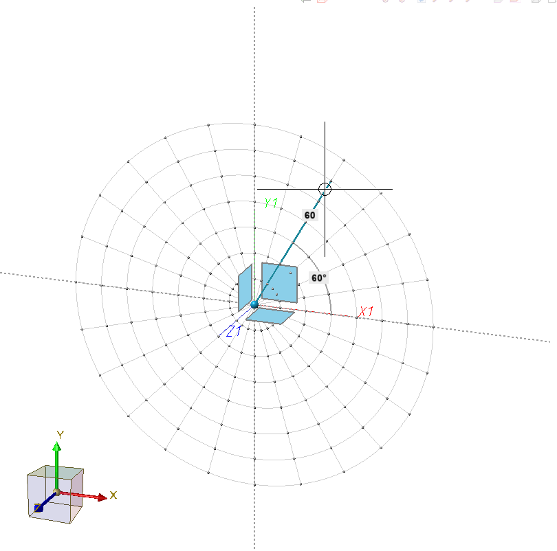
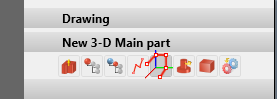
- The function 3-D Sketch is now also available in the context menu for drawings.
- If the automatic assignment of constraints is activated in the Sketch HCM settings (Sketch > HCM > Tools > Settings), the start and end points of the sketch lines and arcs are represented by small blue points from SP1 onwards. The size of the points can be set in the Configuration Editor at System settings > Sketch HCM with the parameter Size of highlighted sketch points.
Dimensionings and Annotations
Automatic dimensioning - Base point optimisation
For automatically generated dimensions, from HiCAD 2020 SP1 onwards, the projection line (for unshortened projection lines) is only drawn to the nearest point on the object to be dimensioned, i.e. to the next point on the contour. This applies to automatically dimensioned developed sheets.
The following figure shows an folded sheet with material subtractions and the automatically dimensioned development of the sheet.
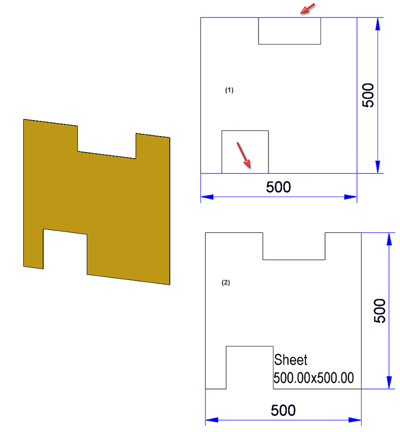
(1) before HiCAD 2020 SP1, (2) from HiCAD 2020 SP1 onwards
![]() Please note:
Please note:
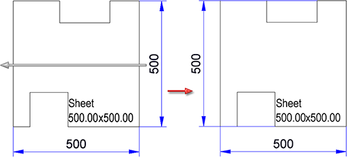
If an automatically generated dimension is changed manually, the optimization described above may not be possible in some cases. This is the case, for example, if you drag the right dimension completely to the other side in the example shown.
Standard compliant information on surface finish
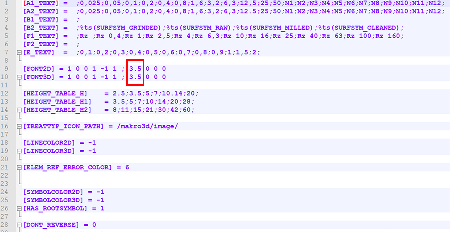
From SP1 onwards, all information on the surface finish is displayed in the same font size and line width. After a new installation of HELiOS, the default setting for the text height of the surface symbols in the surfsym.ini file is 3.5 mm.
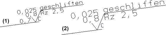
(1) from HiCAD 2020 SP1 onwards, (2) before from HiCAD 2020 SP1
Mark attributes in annotations as favourites
When selecting attributes for annotations, you now have the option to mark frequently used attributes as favourites for a faster access. Simply click on the  symbol next to the attribute name. The symbol then changes its colour to yellow
  . Attributes marked in this way are listed in the selection window under Favourites.
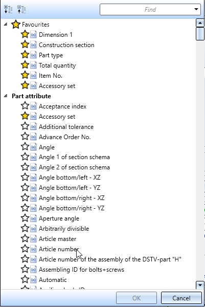
To remove an attribute from the Favourites list, simply click on the corresponding symbol - either directly in the Favourites list or in the attributes list.
Views
Automatic QuickView
For complex model drawings, especially when updating views in HiddenLine mode, waiting times may occur. In order to reduce these waiting times, HiCAD offers the possibility to temporarily use the corresponding Quick HiddenLine representation - the so-called QuickView - instead of the exact HiddenLine calculation for views with long calculation times. This considerably increases performance when editing and updating views. Situations in which this mode is very useful include
- the opening of model drawings with updating of referenced parts or
- switching from the Model view to a sheet area with many views.
The table below shows which QuickView belongs to which exact representation:
|
Exact representation |
Associated QuickView |
|---|---|
|
HiddenLine |
Quick HiddenLine |
|
HiddenLine dashed |
Quick HiddenGrey |
|
Shaded with HiddenLine |
Shaded with edges |
|
Glass model |
Wireframe (not separately selectable) |
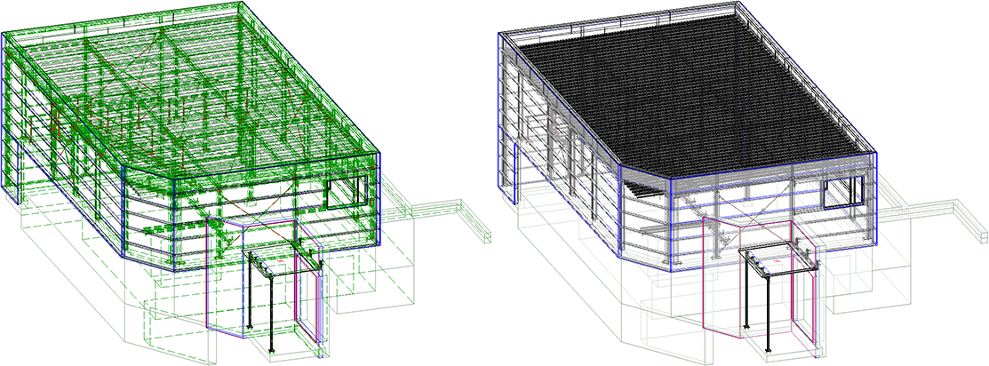
Left: Exact representation - HiddenLine dashed; Right: QuickView - Quick HiddenGrey (Image: Metallbau Wilhelmer Projekt GmbH, Kolbnitz, Austria)
The QuickView can be activated model drawing-dependent, i.e. you can switch the mode on or off depending on the requirements or size of the model drawing. This can be done either automatically or manually. In addition, you can define how the system should proceed when saving if the model drawing contains QuickViews.
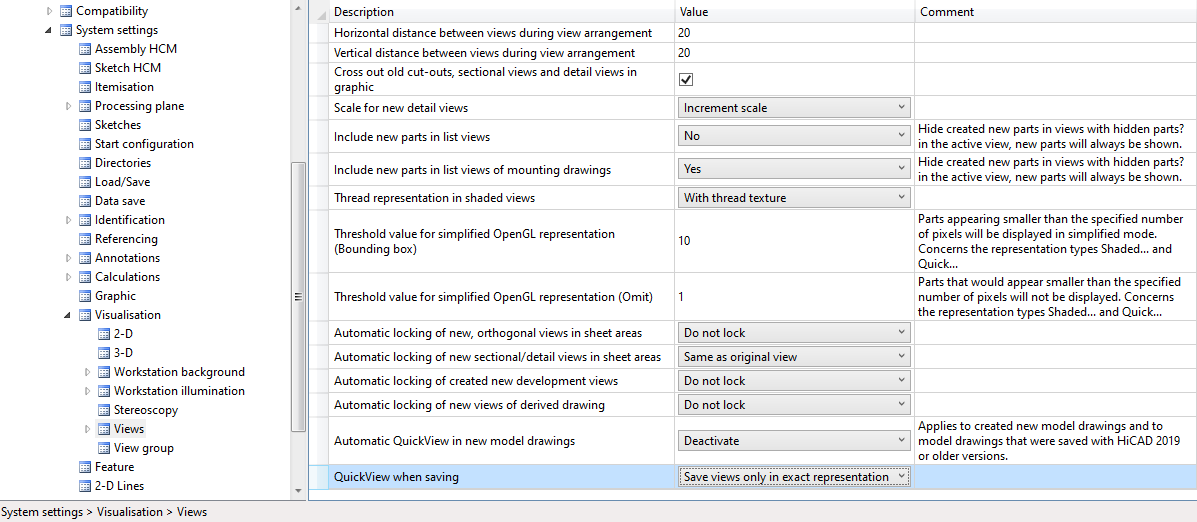
The following parameters are available in the Configuration Editor at System settings > Visualization > Views:
- Automatic QuickView in new model drawings
This setting determines whether the automatic QuickView should become active for newly created model drawings and for model drawings created with HiCAD 2019 or earlier. If the setting Activate is selected, HiCAD automatically decides when the QuickView is required. The I default setting is Deactivate, that is, the QuickView must be activated manually if required. - QuickView when saving
Use this parameter to specify how to proceed when saving if the model drawing contains views in QuickView. The default setting is Save views only in exact representation.
Representation of shaded views with shortening
Since HiCAD 2020, it has also been possible to shorten views for shaded views (Representation type Shaded with/without edges or Quick Hidden Line / Quick Hidden-Grey). However, the shortening marks in shaded views have not been displayed clearly enough until now. As of SP1, these are now highlighted in the colour selected in the shortening parameters for the break lines.
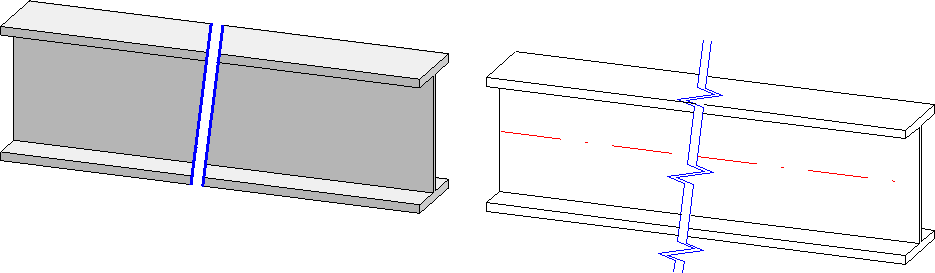
Please note in this context that only the colour is taken into account for shortening shaded views.
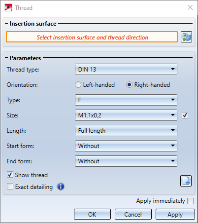
Determine the section direction for views containing shortenings
From HiCAD 2020 SP1 onwards, you have the option of individually defining the section direction, i.e. the direction in which the break lines run. The Shortened view dialogue window has been extended accordingly:
After adding a shortening area, click on Determine, and then define the direction by specifying two points, selecting an edge or selecting a surface. When selecting a surface, the surface normal is used. If you have defined a section direction, the break lines run parallel to the projection of the section direction into the screen plane. Otherwise, the section is always orthogonal to the direction of shortening, i.e. the direction in which the partial areas are pushed together.
Click on Reset to cancel the section direction.
(1) Shortening without section line; (2) Shortening with perpendicular edge as section line
Part properties
Alignment of flanges and bend zones
Since no workshop drawing can be created for sheet metal flanges and bend zones, the alignment selected in the context menu for 3-D parts via Properties > Part orientation always refers to the main sheet metal part from HiCAD SP1 onwards.
Alignments of sheet metal flanges and bend zones that were set in older HiCAD versions (before 2020 SP1) can be deleted using the Reset  function. The main sheet metal part must be active. The view alignment of the sheet metal main part is displayed for these sheet metal straps and bend zones.
Non-dimension relevant assemblies and parts
Not all parts are relevant for the dimensions of assemblies. For this reason, HiCAD offers the option of marking such parts as not relevant for dimensioning. These parts are then ignored in all superordinate parts and assemblies when calculating their dimensions.
To mark a part as "non-dimension relevant", the part attribute Ignore for dimensions (attribute name: #NDR, attribute type: Integer) must be assigned to it. If this attribute has the value 1, it is considered "non-dimension relevant".
To use this attribute, you must manually expand the attribute masks and/or properties windows of the ICN. This attribute is not preset in the masks and windows included in HiCAD's scope of delivery.
You can find an example here.
Standard processings
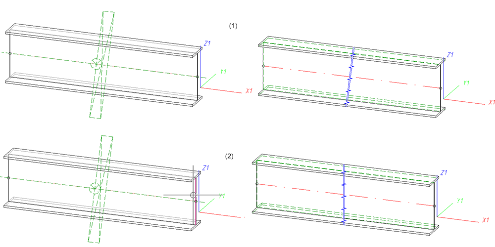
Selectable border mode for hole patterns
For the Hole pattern function you can now specify how to handle holes that cut the border of the processed area and are therefore only partially inside the processed area. The Border mode option is available for this purpose. The possible options are:
- No hole on border: Only holes are created that lie completely within the processed area (corresponds to the behaviour of older versions).
- Complete hole on border: Every hole that lies partly or completely within the processed area is created completely.
- Intersect hole with border: Holes that lie only partially within the processed area are only partially created.
(1) Template: Hole with area to be processed; (2) No hole on border; (3) Complete hole on border; (4) Intersect hole with border
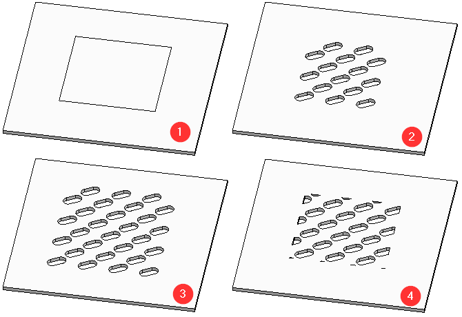
Extended Thread dialogue window
The Internal/external threads  function has been extended:
- Instead of a cylinder surface you can now also choose an edge on one side of the cylinder.
- The thread texture will be displayed in a preview.
- You can now define the start and the end of the thread.
The following options are available:
|
External thread |
Internal thread |
|---|---|
|
Without |
Without |
|
Chamfer |
Countersink The countersink will only be created if the Exact detailing checkbox has been activated. |
|
Cone point |
|
|
Tapering |
|
(1) Without, (2) Chamfer, (3) Cone point, (4) Tapering
Internal thread with and without countersink
Major Release 2020 (V 2500)
Create parts
Dependent parts
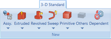
The Dependent part  function has been moved into the New function group of the 3-D Standard Ribbon tab.
Part CS of assemblies
Like any other part, assemblies, too, have a part coordinate system. This coordinate system can either (as previously) be automatically determined by HiCAD, or (from HiCAD 2020 onwards) determined by you during creation of a dummy assembly or during forming of an assembly from existing parts. For this purpose, a new parameter is available in the ISD Configuration Editor at Modelling > Part creation > Assembly.
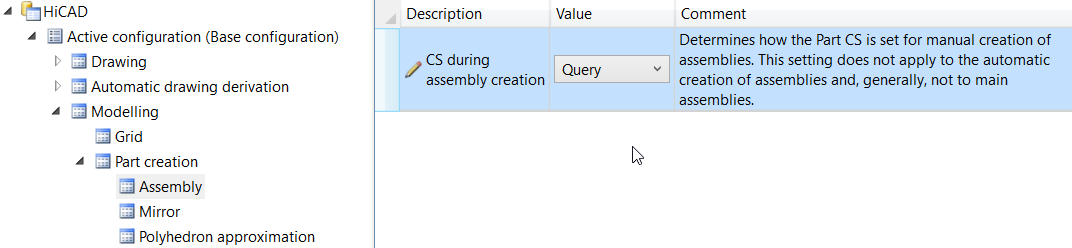
The following settings are possible:
- Standard CS (default)
The Part CS will be determined automatically by HiCAD and corresponds to the World CS. There will be no further queries. This behaviour is identical to that of previous versions. - Query
If this setting is active, HiCAD will ask you to choose a plane, as you would do for a processing plane. This plane is the top view plane of the Part CS. You have the following options to determine this plane: - You determine the plane by identifying, in any order, points, edges, surfaces and also processing planes in the model drawing. The standard CS will then be rotated in such a way that the XY-plane lies in the selected plane.
- Press the middle mouse button to choose the World CS.
- Right-click to activate a context menu with further functions.
The functions of the menu work in the same way as the same-named functions for processing planes.
The settings in the Configuration Editor do not apply to main assemblies. For created new main assemblies the Part CS always corresponds to the World CS.
Views
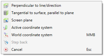
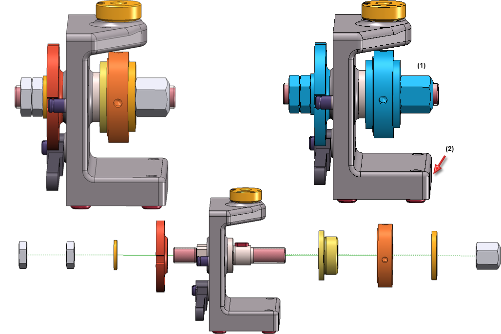
Exploded view with AutoDirection
HiCAD 2020 features a new movement type called AutoDirection  on the Exploded view Ribbon tab.
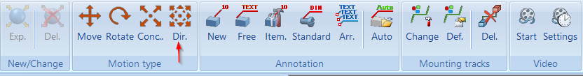
This function allows you to define displacements with automatic direction in the Exploded view mode. As with the displacement, several parts are linearly displaced simultaneously. In contrast, these parts are not moved with the same distance, but are distributed along the selected direction relative to a certain part (the so-called fixed part). This makes it possible to move several parts simultaneously in positive and negative direction in one step - depending on the position of the parts in relation to the selected fixed part.
In the image below, take a look at the initial drawing shown on the left. We want to achieve that the selected parts (1) - highlighted blue in the figure - are moved on both sides of the fixed part (2) in one step, depending on their position relative to part (2). The desired result is shown in the figure below. This can be achieved with the AutoDirection function.
New icons for Show/Hide parts
The icons for the Show/Hide parts functions in 3-D views have been replaced with new and more descriptive icons. This concerns both the functions on the Views Ribbon and the functions in the context menu for views. This concerns the following functions:
 Hide parts in active view, Individual (Views > Parts > Hide)
 Hide all parts in active view and show individually (Views > Parts > Off/On)
 Show parts in active view, Individual (Views > Parts > Show)
 Show all parts in active view (Views > Parts > ShowAll)
Visibility of textures in the HiCAD Viewer
The settings for the representation of textures (at Views > Representation > Shaded > Shaded representation) will now be considered for the representation of textures. This means that whether and in which view the textures will be shown in the Viewer will depend on the above settings.
Settings for shaded representation
The functions Shaded representation, active view and Shaded representation, all views have been renamed and now have new icons:
 Settings for shaded representation, Active view
 Settings for shaded representation, All views
Shortened views
In HiCAD 2020 a shortening of views is also possible for shaded views.
Up to now, views were created with the representation type
- Shaded with/without edges or
- Quick HiddenLine / Quick HiddenGrey
is always shown unshortened, even if the view was actually shortened. For drawings created with versions before HiCAD 2020 and containing such views, the Configuration Editor at Compatibility > Views allows you to define how to open these drawings.
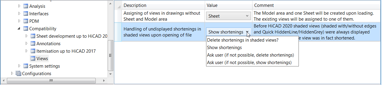
The default setting is Show shortenings.
Simulation
Discontinuation of "old" assembling simulation
The old functions Assembling simulation and Simulation (Compatibility) that could be reached via the toolbars (Settings > Toolbars have been discontinued and will be no longer available as of HiCAD 2020. For the creation of simulations, please use the functions of the Simulation docking window.
Dimensioning
Dimension assignment
In previous versions, dimensions were always assigned to the active part during their creation. From HiCAD 2020 onwards, you can assign the dimensions either to the active part or to the part to which the 1st dimension base point belongs. This behaviour can be determined via the Set parameters for new general dimensions function, on the System tab of the dialogue window.
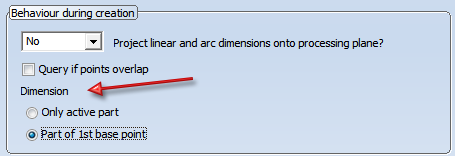
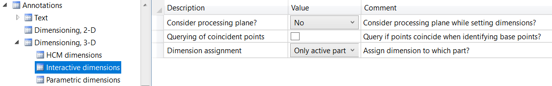
The parameters of this tab can be preset via the Configuration Editor, at System settings > Annotations > Dimensioning, 3-D > Interactive dimensions > Dimension assignment. The default setting is Active part.
Texts+ Annotations
Part annotation settings
The Part annotation Settings  function can now be found at 3-D Dimensioning+Text > Text > Annot. > ... .

Delete part annotations
The Delete functions for part annotations can now be found in the pull-down menu of the Delete text  function:
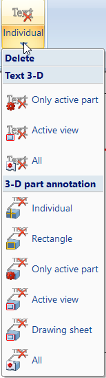
New in this menu is the function Delete 3-D part annotation, drawing sheet 
Changed attribute selection dialogue
HiCAD and HELiOS attributes can now be selected directly in the Annotation Editor. To do this, click on the Attributes button and select the desired attribute from the selection list.
The list is divided into the different attribute groups
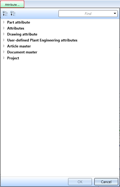
The selection list can be expanded, collapsed and searched for specific entries.

Revised 3-D text
- The handling of 3-D texts has been revised. From HiCAD 2020 onwards, texts that are newly inserted into the model drawing can not only be selected via their reference point, but also via any point on the text. This facilitates selection and increases performance. In addition, the text is automatically generated with an exclusion.
- The functions
- Copy active text and move via 2 points (3-D) and
- Move text, via 2 points (3-D)
are no longer available.
- The default settings for fonts can be set in the Configuration Editor, separately for 2-D and 3-D texts, at Drawing > Annotations > Text.
Standard parts/processings
Revised Threads function
The function 3-D Standard > Standard Processings > Thread for the creation of internal and external threads has been revised completely. and outer
Processing direction
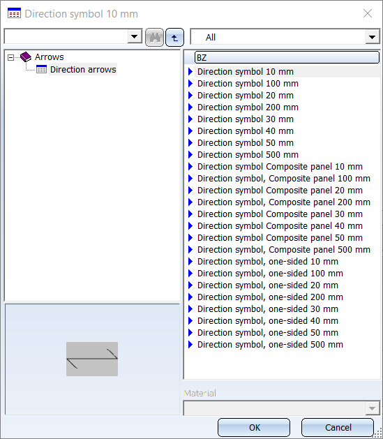
New symbol sizes are available in the table Direction arrows (in the catalogue Factory standards > Symbols > Arrows). These are available to you when you choose the Processing direction  function.
Standard processings / Slots
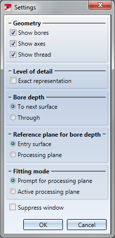
- In the Settings for Standard Processings the Through dialogue text has been replaced with Unlimited.
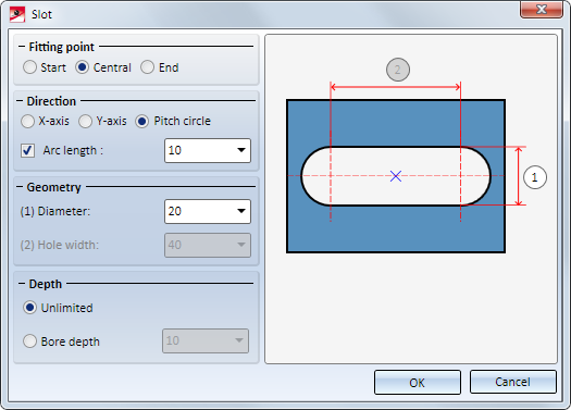
- In the dialogue window of the Slot function the Through checkbox has been replaced with the options Unlimited and Bore depth.
Sketches
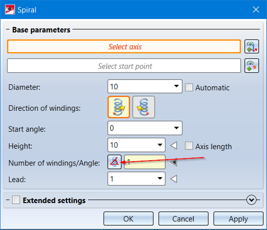
Spirals
In the dialogue window of the Spirals  function you can now also specify a winding angle instead of a number of windings. Use the
  and
and  symbols to switch between the options.
|
|
If this symbol is visible, the Number of windings mode is active. Enter the number of the required windings. The winding angle will be calculated automatically. |
|
|
If this symbol is visible, the Winding angle mode is active. Enter the required winding angle. The number of windings will be calculated automatically. |
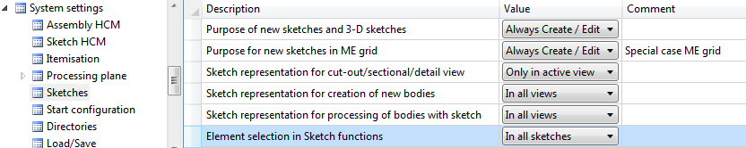
Element selection in Sketch functions
In some drawings in can happen that sketches or sketch lines are hidden by other sketches or sketch lines in front of them.To prevent accidental deleting or trimming of the wrong sketches or sketch lines, HiCAD offers you the option to determine whether you can only select lines of the active sketch, or the lines of all sketches when you use these functions. This behaviour can be determined in the Configuration Editor at System settings > Sketches > Element selection in Sketch functions. The default setting is In all sketches.
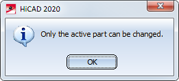
If the setting Only in active sketch is active, the following message will be displayed when you select a line of a non-active sketch with the corresponding functions:
Preview of processing planes when creating sketches
If the World CS planes for new sketch (also 3-D sketch) checkbox is active in the Novice configuration, a preview of the planes of the world coordinate system will be displayed when creating new sketches. You can then simply use the cursor to select one of the default planes displayed as a preview.
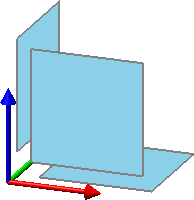
This preview is now considerably larger.
New Sketching Tool for 3-D sketches
Similar as for planar sketches, the new 3-D Sketching Tool is now available for 3-D sketches as a convenient tool for creating three-dimensional polylines.
If a 3-D sketch is active, the 3-D Sketching Tool will be automatically started when you choose the Line  (Sketch > Draw > Line) function.
The Sketching Tool simplifies the design process by automatically displaying auxiliary lines along a predefined grid starting from the last point of a line and displaying the corresponding angles, distances or radii at the cursor depending on the selected mode. On this grid you can, for example, determine the direction and length of a line with a mouse click by appropriate cursor movements. Since 3-D sketches - like other 3-D parts - have a part coordinate system, you can change the plane in which you are drawing as you wish while drawing. This drawing plane is always parallel to the selected plane and runs through the last point determined.
Model and process parts
Hide points/crosshairs
The functions
 Hide point and

will now remain active after selecting a point/crosshairs edge, i.e. you can select further points/crosshairs edges to be hidden. Press the MMB to exit the function.
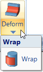
Wrap function moved
The Wrap  function can now be found in the pull-down menu of the Deform
  function.
Automatic calculation of assembly dimensions
For assemblies, the dimensions of the parts belonging to the assembly can be used to automatically generate the attributes Length, Height and Width of the assembly and enter it in the assembly attributes. All solid parts belonging to the assembly are included in the calculation, with the exception of standard and purchased parts with the insertion type Site assembly.
Excluded from the automatic calculation are structure assemblies.
Whether and when the assembly dimensions are calculated when parts are changed can be set in the Configuration Editor, namely at Modelling > Part properties > Calculate assembly dimensions.

The following settings are possible there:
- Do not calculate automatically
The attributes of the assembly are not updated. This is the default setting. - Only during itemisation
The attributes are only updated during itemisation. - Always
The attributes of the assembly are updated immediately, i.e. after each change to the components or after adding further components.
To calculate the dimensions, a bounding box for the assembly is determined internally, i.e. the smallest cuboid that completely encloses the parts of the assembly to be considered.
- The orientation of the bounding box also plays a role in the calculation of the dimensions. This is determined according to the following priority:
- Alignment of the changed or newly added part, i.e. the view selected in the context menu for Parts at Properties > Part orientation.
- Alignment of the assembly main part
- Coordinate system of the assembly main part
- Coordinate system of the assembly itself
The first option that is available is used. Since each assembly has a part coordinate system, there is always a usable orientation and the dimensions can be calculated.
The assignment of coordinate system axes to the values is
- x: Length
- y: Width
- z: Height
If the part orientation (point 1 or 2) is used, length/height is derived from the front view and the width is perpendicular to it. This assignment is not configurable.
