Right-click > Properties > Part orientation
Use these functions in the context menu of 3-D parts to specify for assemblies, general 3-D parts, beams, Sheet Metal parts, Steel Engineering plates and pipelines whether the active view of a derived drawing is to be considered to be the
 Front view or the
 Top view.
This setting influences the alignment of the assemblies, parts, beams, sheets and plates in derived drawings as well as the pipelines in isometries and pipe spool drawings.
The orientation is also considered for the calculation of assembly dimensions.
If you want to undo the chosen alignment, Reset  .
.
The chosen alignment is marked accordingly in the drawing:
Left: Active view as front view; Right: Active view as top view
If the assembly or the view is rotated, the marking of the parts will be adjusted accordingly:
The visibility of the marking can be switched on or off via the settings in the Configuration Editor at System settings > Visualisation > Show alignment of active 3-D part in drawing:
- Never
The marking indicating the alignment is never shown. - Always
The marking indicating the alignment is always shown (provided that an alignment has been specified). - Switch on/off with F6 key
The marking indicating the alignment can be shown or hidden with the F6 key. This is the default setting. If this setting is active, the alignment marking can also be shown/hidden via the Coordinate systems toolbar (at the bottom of the dialogue window) by clicking on the icon.
icon.
 Important:
-
When applying the view as front view
or as top view to beams and plates, HiCAD will check whether the new alignment is actually allowed. Please note the following:
- Top views of plates must be perpendicular to the upper or lower plate side!
- Front views of beams show either the front side or the rear side of the web.
- Front views of round profiles must run horizontally, while allowing a free rotation about their axes. This enables a rotation of the view-defining coordinate system for trimmed round beams in such a way that the cutting angle can be dimensioned in the workshop drawing.
The result of the check will then be shown in a dialogue window. Here it will be listed for which of the chosen plates the new alignment was successful, and to which no new alignment could be applied.
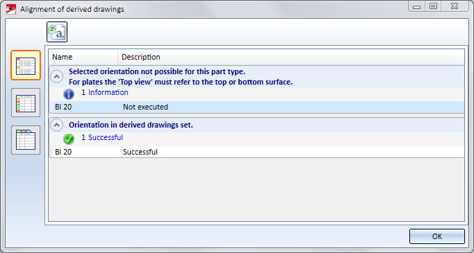
Use the symbols on the left to switch between the following representations of the list:
 Detailed list
 Abridged list
 List with several tabs
Click the  symbol to save the result list as a CSV file.
- Since no workshop drawing can be created for sheet metal flanges and bend zones, the alignment always refers to the main sheet metal part. Alignments of sheet metal flanges and bend zones that were set in older HiCAD versions (before 2020 SP1) can be deleted using the Reset function. The main sheet metal part must be active. The view alignment of the sheet metal main part is displayed for these sheet metal straps and bend zones.


Part Properties (3-D) • Surface, Line ans Edge Parameters • Colour Editor • Model and Process Parts (3-D) • Derived Drawing - Active View as Front View/Top View