Project: HiCAD Point Cloud
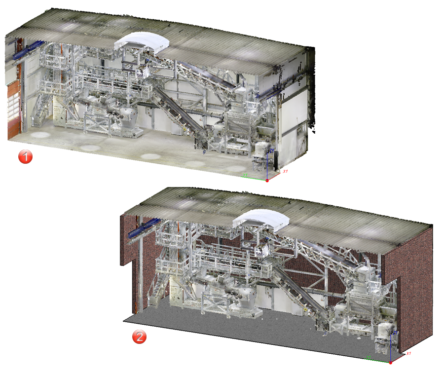
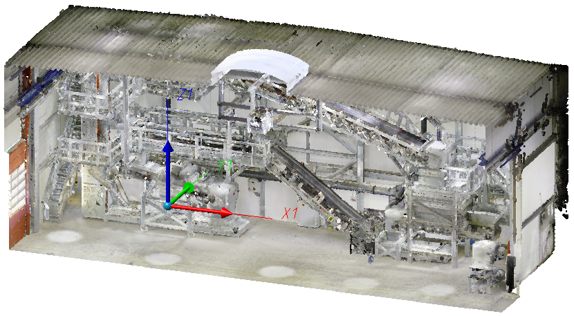
(1) Point cloud in HiCAD
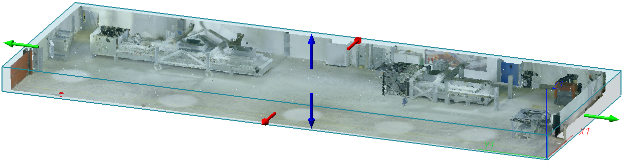
(2) Point cloud with hall

 .
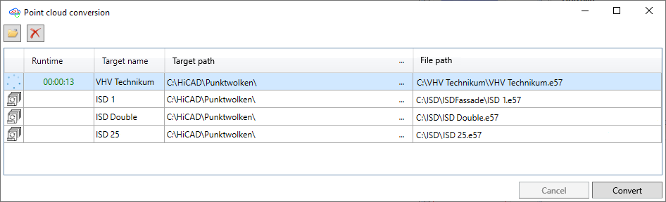
. The converter will then be started.
 to load the prepared 3-D scan (e.g. *.E57).
 Drive N (..\HiCAD\Punktwolken\) from Filegrup.DAT is preset as the target path.
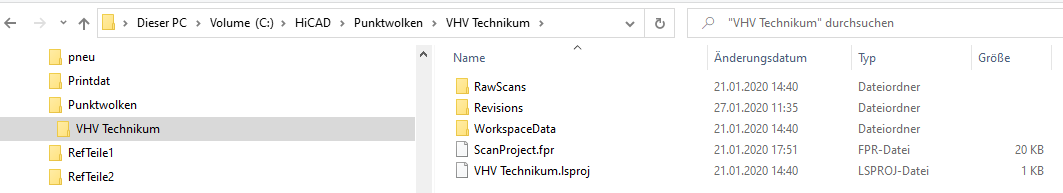
After the conversion you will find the point cloud file *.LSPROJ in directory N (Filegrup.DAT).
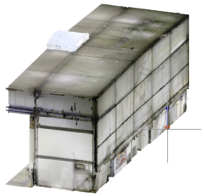
 to load the *.LSPROJ file into your HiCAD model drawing.
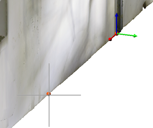
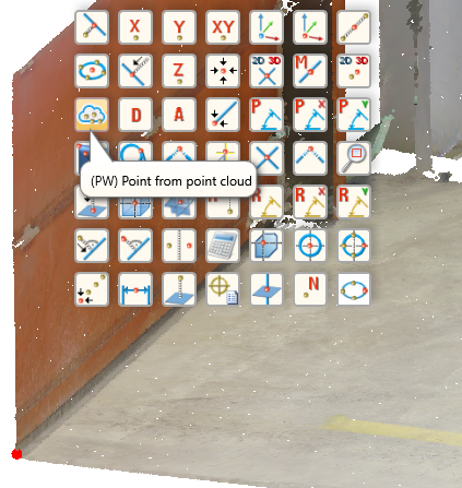
To determine the point cloud points, HiCAD automatically activates the point option (PW) Point from point cloud  .
.
After determining the points the point cloud is rotated in such a way that the Part CS coincides with the World CS.
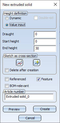
To sketch the floor you need to create a so-called clipping of the point cloud.
 function.
Use the Sketch functions to redraw the floor.
 and select the plane using the point option (PW) Point from point cloud .
 function.
 function.
Now retrace the wall:
and select the plane using the point option (PW) Point from point cloud point option. function to redraw the wall.
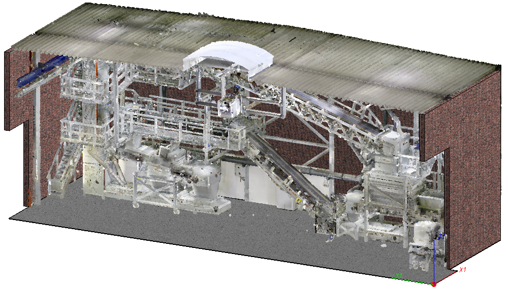
With the help of the point cloud, you can quickly transfer the dimensions of a hall into your drawing.

Procedure • Point Cloud Functions
|
© Copyright 1994-2020, ISD Software und Systeme GmbH |
Data protection • Terms and Conditions • Cookies • Contact • Legal notes and Disclaimer