
Project: HiCAD Sheet Metal
The new user-friendly Insert bend zone  function brings together the previous functions in the Bend zone function group on the Sheet Metal tab. A major advantage is the insertion of milling edge zones for composite sheets.
The Insert bend zone function allows you to subsequently join the flanges of a sheet metal part to a bend zone. The sheets are shortened so that the height or length does not change. The amount of the shortening depends on the bend radius.
The length of the bend zone can be determined by 2 points. To avoid shortening the connecting sheet you can choose between clearance and a relief groove.
If the width of the connecting sheet is different, a cut is inserted. The depth of the sheet on which the attachment is made is retained.
All entries are recorded in the feature log and can be altered there later.
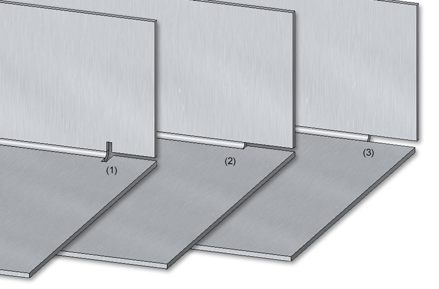
(1) Bend zone with relief groove
(2) Bend zone with clearance
(3) Bend zone with shortened flange, without relief groove
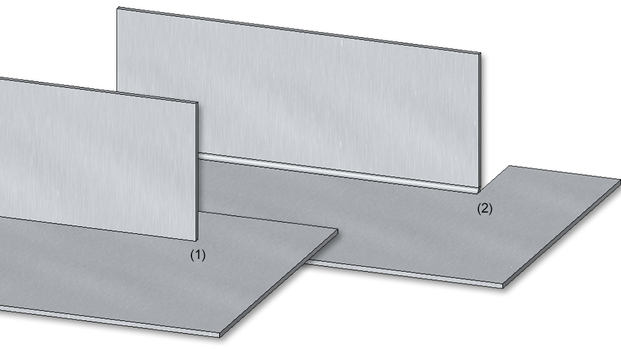
(1) Original situation
(2) Different flange widths with cut and clearance
The bend tools Die and Punch defined in the LVD Bend zone tooling can now be displayed in the development bend line text.
The selection is made in the development settings when editing the bend line texts.

Then select the Die and Punch attributes in the text editor.
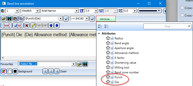
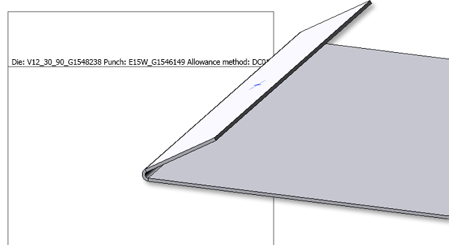
If an assigned tool exists for the bend zone, the names of these tools can now be inserted in the bend line texts.
The names are the entries in the BZ column in the corresponding bend tool assignment tables "LVD Die - Table" and "LVD Punch - Table" from the Catalogue Editor.
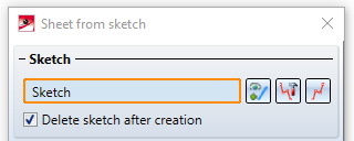
The dialogues of functions requiring the selection of a sketch,
have been slightly modified. The functions Process sketch  and New sketch in plane
  can now be accessed immediately in the dialogue window.
The Design Checker has been extended by a new check called Sheet must contain exactly 1 direction symbol. This allows you to find all sheet metal parts that are not assigned exactly one direction symbol.
From HiCAD 2020 SP2 on, Steel Engineering plates can be coated like Sheet Metal parts. Therefore the functions
can now be found in the Further Functions function group of the Steel Engineering tab.
In the Process function group of the Sheet Metal tab, these functions have been combined in the Coating function.
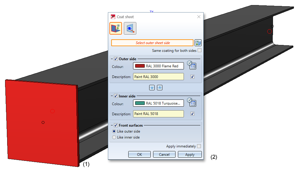
(1) Steel Engineering plate,
(2) Coating settings
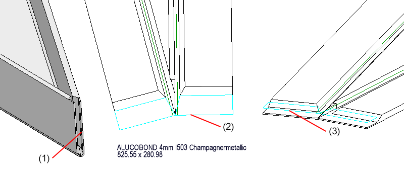
When using ALUCOBOND SZ-20 tray panels , there is sometimes the desire to create a connection with a flange for the side connection in practice, so that a "U" is created. This application cannot be realized directly via the Element installation dialogue window, but rather via the design variant Flange for SZ-20 in the Civil Engineering functions at Sheet Metal docking window. Until now, this variant could only be applied to SZ20 cassettes with vertical section = standard. As of SP2, it is now possible for all connection types, e.g. for the Attic, short connection.

(1) Element installation "Attic, short" without flanges
(2) Attaching of the flange and calling of the Design Variant with selection of the highlighted edge
(3) Result
From HiCAD 2020 SP2 onwards, the viewing direction of the sectional views of sheet metal parts in the workshop drawing is to the right or downwards. Aligned cuts are positioned to the right or down, accordingly.
(1) Sectional view in workshop drawing - Before HiCAD 2020 SP2
(2) Sectional view in workshop drawing - - From HiCAD 2020 SP2 on
![]() Please note:
Please note:
Updating your existing drawings may alter the position of the sectional views.
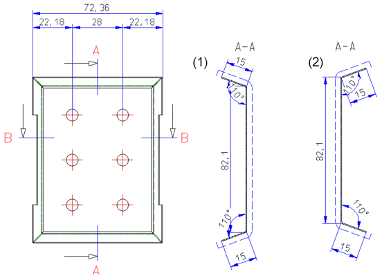
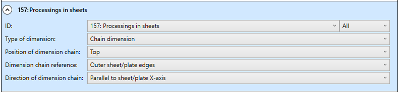
In the configuration for the usage DEFAULT(KANTBLECHE) (DEFAULT (SHEETS)) the dimension rule 157: Processings in sheets is now additionally preset for the front view and the top view as follows:
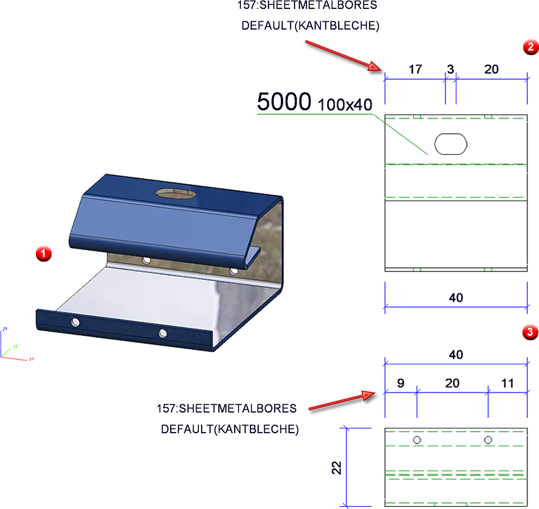
(1) 3-D model,
(2) Front view
(3) Top view in the workshop drawing
The selection of base points for automatic dimensioning of contours has changed. This change affects sheet metal parts (including their developments), steel engineering plates and glass panes.
Previously, when dimensioning contours, the end points of the individual edges were dimensioned. However, this is usually not desired in practice. From SP2 on, the following base points are taken into account for contour dimensions:
Outer contours
Bores and subtractions
 > Dimensioning Settings.

This change affects the dimensioning rules for outer contours and holes/subtractions of sheet metal parts (including their developments) steel engineering parts and glass panes.
The new processing functions for 3-D developments can be activated by right-clicking on the development and selecting the Process development function .
With the following functions:
you can insert holes, create subtractions, attach sweep bodies and cut parts on the basis of a planar sketch.
If you have selected the New sketch option in the dialogue window, HiCAD automatically activates the Sketch tab. Use the functions on this tab to create the sketch. For sketch-based functions, you can use the Information menu functions during creation or processing of the sketch.
Only the closed polylines of a sketch are considered.

With the function Suppress sheet update  (right click on a development) you "freeze" the development for changes. This means that changes to the sheet metal part will not be transferred to the development. In the ICN these developments are marked with a star symbol.
For automatically generated dimensions, such as in sheet developments, from HiCAD 2020 SP1 onwards, the (unshortened) projection line is only drawn to the nearest point on the object to be dimensioned, i.e. to the next point on the contour.
The image below shows a Sheet Metal construction with subtractions and the automatically dimensioned development of the sheet.
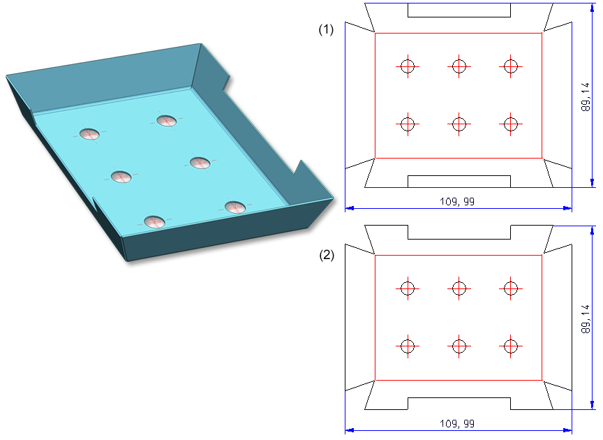
(1) Automatically dimensioned development, older versions
(2) Automatically dimensioned development, from HiCAD 2020 SP1 onwards
![]() Please note:
Please note:
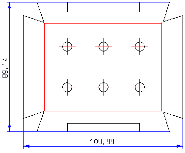
If an automatically generated dimension is changed manually, the optimization described above may not be possible in some cases. This is the case, for example, if you drag the dimension on the right completely to the other side in the example shown below.
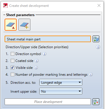
When choosing the Sheet alignment:Automatic  option for a sheet development, the definition of the visible sheet side can now be taken into account. This is done with the new Determine visible side
  function in the Process function group.
In order to fold Sheet Metal cassettes with milling edge zones better and more easily, the milling edge zones are often extended a little at the intersection points. You have the possibility for milling edge zones to extend the bend line on the Milling+Folding tab of the Extended settings dialogue window. There, activate the Lengthen milling lines checkbox and enter a value.
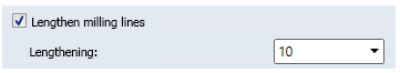

Lengthening of bend lines in the development
The new Determine visible side  function lets you define the upper side of a Sheet Metal part. This side can then be taken into account during development or coating. Identify the side using a surface or two edges. Then you can determine the visible side for further Sheet Metal parts or execute the function with the middle mouse button. For deleting, the Delete visible side
  function is available in the pull-down menu.
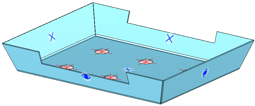
The visible side is marked with these  icons . The other side is marked with X icons
  .
.
Sheet Metal parts that have been assigned an identifier for the visible side are taken into account for identical part search. For example, if the model drawing contains two Sheet Metal parts of the same size, one of which has an identifier for the visible side, the sheets will not be considered to be identical and are assigned different item numbers.
Sheets that were previously marked with the Determine visible side function can now be taken into account when coating the sheets with multiple selection  .
.
If you have called the coating dialogue, the Via visible side  option is now available. You can then add several sheets with a visible side to the list and assign the coating colour (RAL, NCS and System colour or Drawing colour) and the coating type Visible side, Back side and Front surface) with Apply.
Right-click on a Sheet Metal part to remove it from the list. If you want to select more sheets, select the  icon for identification.
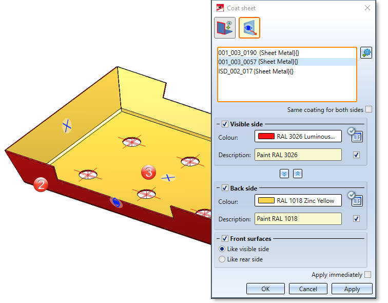
(1) Select Sheet Metal parts via visible side
(2) Visible side
(3) Back side
The Sheet from solid function has been reworked for convenient generation of Sheet Metal parts. In addition to individual selections, multiple selections are now also possible. Here you can select the parts in the model drawing after calling the function. If you have activated an assembly or several main parts in the ICN before you call the function, these parts also appear in the list of active parts.
The preview of the new sheet is also displayed. Choose Mode to select the evaluation type for sheet thickness.
|
Sheet thickness from semi-finished product |
In this mode you select the sheet thickness with semi-finished product. |
|
Automatic sheet thickness from semi-finished product |
The sheet thickness is automatically selected to match the selected semi-finished product. |
|
Sheet thickness, from solid |
The sheet thickness is taken from the solid. |
|
Sheet thickness, value input |
The sheet thickness is entered directly. |
If the initial part contains chamfers, these are transferred to the sheet metal part..

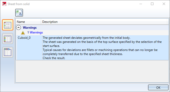
If deviations from the geometric initial body occur during generation, they are listed after the sheet metal parts have been generated:
For the Sheet Metal Design Variants the Favourites management is now also available.
The settings of the various dialogue windows can be saved as favourites and reused at any time. To do this, click on the  symbol at the bottom left of the dialogue window.
The Favourites supplied with the software are only examples and may have to be adapted to your company's specific needs. You can find more information on Favourites Management in the HiCAD Basics Help.

When using the design variant Sheet corner with stiffener it is now possible to choose whether standard parts (rivets, screws etc.) should be installed or not. For this purpose, the checkbox Insert standard parts has been added to the dialog box. The default setting is that standard parts are created, i.e. the checkbox is active
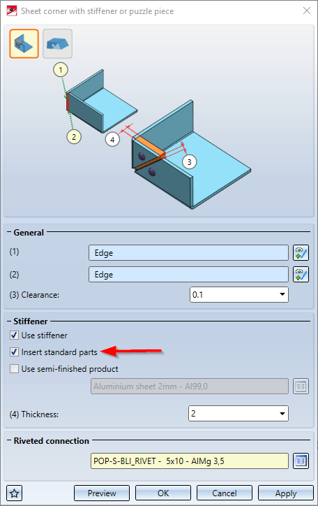
If the checkbox is not active, the standard parts will not be listed in the BOM.
For Sheet Metal parts, you can use the Properties > Part orientation function in the context menu (right-click) to define which view is to be the Front view  or the Top view
  for the orientation of derived drawings (workshop drawings).
Since workshop drawings cannot be created for sheet flanges and bend zones, the orientation from HiCAD 2020 SP1 onwards always refers to the sheet metal main part.
You can delete orientations of sheet flanges and bend zones that were set in older versions using the Assignment reset  function. For resetting, the Sheet Metal main part must be active. The view orientation of the main part is displayed for these sheet flanges and bend zones.
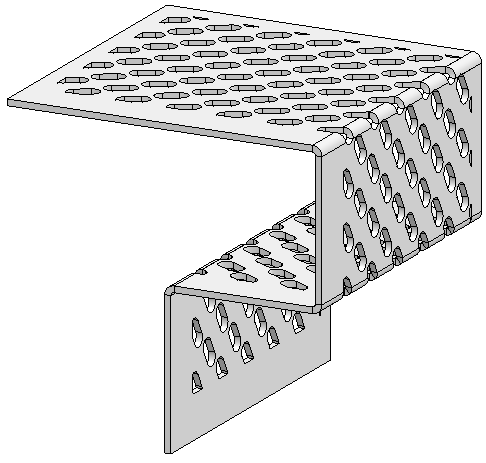
Hole patterns can now also be applied to sheet developments.
You can now use the Sheet Metal cassette Design Variant to create Sheet Metal cassettes with milling edges zones and inverted milling edge zones. To do this, simply select the desired Mode on the Attach flange tab of the dialogue window.
Sheet Metal cassette with milling edge zone
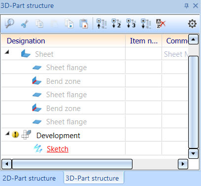
Sheet developments can now be edited with assigned sketches. To do this, you can select the new Sketch (sub-part)  function by right-clicking on the development in the menu that appears before processing. After placing a processing plane, draw a sketch, for example, for a subtraction. The ICN now displays the development with the sub-part called Sketch. This allows you to activate the sketches you have created in advance when you process the development, for example, with the 3-D function Subtract, with translation
 ![]() . The processing plane is visible if it is switched on via Show/Hide elements for the view. If the sketch is generated from the dialogue window of the processing function, it is also located in the ICN under the development.
. The processing plane is visible if it is switched on via Show/Hide elements for the view. If the sketch is generated from the dialogue window of the processing function, it is also located in the ICN under the development.
With the following functions on the 3-D Standard tab you can now also process developments:
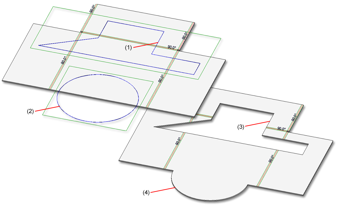
(1) Sketch for subtraction
(2) Sketch for addition
(3) Subtraction
(4) Addition
The development now also appears in the ICN below the Sheet Metal part and can contain sketches as sub-parts. If the development is active the sheet metal part is greyed out. Activate the development in the drawing or by selecting the view.
You use the Show milled area option to mark exclusions that you have defined, e.g., with the 3-D function Subtract part, via translation ![]() . For the triangular SZ-20 panel in Element Installation, too, the material in the "acute corner" will be excluded (milled away). The milled area will be recognized when creating the development. That is, facets which are no cover facets, which run parallel to the cover surface, and which have no standard processings form the milled (i.e. subtracted) area.
. For the triangular SZ-20 panel in Element Installation, too, the material in the "acute corner" will be excluded (milled away). The milled area will be recognized when creating the development. That is, facets which are no cover facets, which run parallel to the cover surface, and which have no standard processings form the milled (i.e. subtracted) area.
To prepare this area for machining, for machine control during DXF output, a layer must be defined for this milled area.

If you activate this option, the edges of the milled area will be entered in the development. The edges are sorted and oriented as specified for inner cycles. Milled areas are combined across milling edge zones.
The generation is activated in the development Favourite for Cobus NCAD: Color 10, Continuous line, Layer 10 In HCADACAD_COBUS.DAT the layer assignment MILLING is defined for the DXF export.
(1) Exclusion in Sheet Metal panel
(2) Exclusion in development (top view)
(3) Exclusion in development (Isometry)
If you move the mouse over a bend line text during 3-D development, the text will be displayed in magenta. If you now move the cursor over the text, press and hold down the leftmouse button, you can move the text. If you move the bend line text along the bend line, the position will now be retained after updating the development.
If you choose ToPS GEO, you can determine via the Export forming edges option, whether processings (forming tools, cross-breaks) are to be considered for export.
When generating the DXF export files for Sheet Metal blanks, the orientation of the polylines in the created DXF file will now always be always the same (i.e. always clockwise or always anticlockwise), since CAM programs require these for determining the outer/inner side when generating the milling tool paths.
The orientation of closed lines can be set when exporting sheet metal developments. In the Configuration Editor at Sheet Metal > Sheet development you can set a clockwise (activate checkbox) or anticlockwise orientation (deactivate checkbox) for the inner and outer contours.
When generating a sheet from a solid with two countersinks with a conical surface (e.g. DIN74) on 2 sides, the geometry is correctly recognized regardless of the start surface.
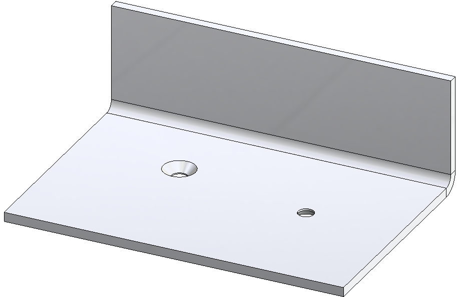
Sheet from solid, with 2 countersinks (DIN74) on two sides
The old Sheet from solid function has been replaced with the same-named new function at Sheet Metal > New. The old function could still be accessed by right-clicking on a bend zone and choosing New > From solid.
When using ALUCOBOND® SZ-20 tray panels, there is sometimes the wish to create a connection with a flange at the side of the panel.
This application cannot be realized directly via the Element installation dialogue window!
To create such a connection, proceed as follows instead:
Example:

(1) Element installation without flanges
(2) Attaching of flange with 35mm side flange, calling of the Design Variant and selection of the highlighted edge
(3) Result
Please make sure to observe the following instructions:
The macro only applies to ALUCOBOND®SZ-20 tray panels where the standard connection is selected for the vertical section.
The side connection is installed without stiffeners.
No automatic connection to the sub-structure is possible, therefore the checkbox Create screws for sub-structures in the Extended settings of the Element installation should be inactive.
The settings on the dialogue window of the Sheet corner with stiffener or puzzle piece Design variant can be saved as favourites and re-used at any time. To do this, click on the symbol at the bottom left corner of the dialogue window. More on favourites management can be found in the Manage Favourites topic of the HiCAD Basics Help chapter.
The user guidance texts in the info bar at the bottom left have been improved for the functions Cut off corner and Create base sheet for an easier operation.
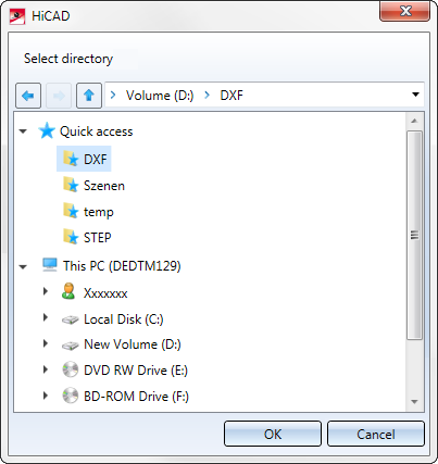
As with the dialogue for loading and saving of files, selected directories can now also be added to the Quick Access folder, e.g., for DXF export of Sheet Metal parts.
The settings of the ABWPOL.DAT file have been moved to the Configuration Editor (ISDConfigEditor.exe).
You now find the settings for the neutral axis for approximative sheet development at Sheet Metal > Default setting.
New arrow sizes have been added to the Direction arrows table (in the catalogue Factory standards > Symbols > Arrows. They are available when you choose the  Processing direction function. (3-D Standard > Standard Processing > Bore > Processing direction).
From HiCAD 2021 onwards, the calling of the old Sheet Metal base sheet macro 'abwgrundblech.mac' will no longer be supported.

HiCAD Sheet Metal • General Notes on Sheet Metal Processing • Overview of Functions (3-D SM)
|
© Copyright 1994-2020, ISD Software und Systeme GmbH |
Data protection • Terms and Conditions • Cookies • Contact • Legal notes and Disclaimer


