3-D Standard > -Standard Processings > Bore  > Hole pattern
The Hole pattern function allows you to insert defined patterns of holes into solids such as parts or Sheet Metal flanges.
For the holes you can choose between round holes, square holes and slots. Besides, you can also use self-defined shapes of holes. For the patterns of the holes you can use DIN-compliant Straight rows, Staggered rows and Diagonally staggered rows of holes. The definition of Freely staggered rows is also possible.
Hole pattern can also be set on flat surfaces of each part; even processed sheet metal can be used, i.e. after applying a bending simulation.
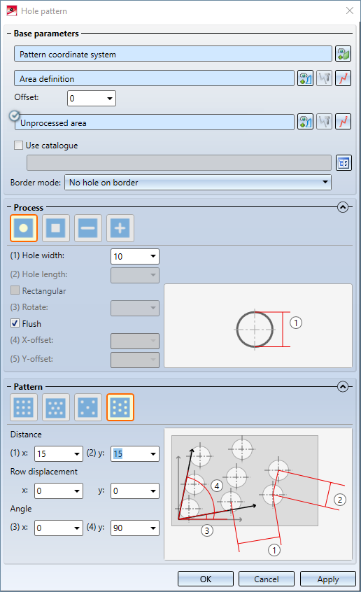
- The "Hole pattern" dialogue window
- Pattern coordinate system
- Processed area
- Offset
- Omitted area
- Use catalogue
- Process
- Parameter
- Patterns
- Parameters
- Row displacement
- Feature log entry
- Example
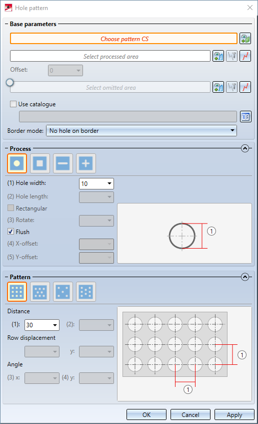
The "Hole pattern" dialogue window

Pattern coordinate system
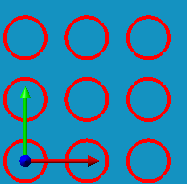
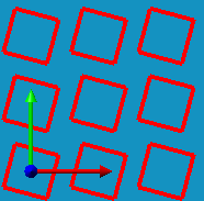
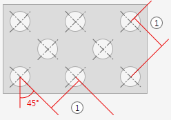
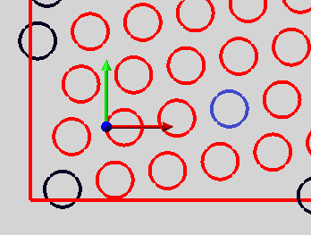
When you call the function, HiCAD will first prompt you to choose a so-called "Pattern coordinate system" (short: Pattern CS). This coordinate system is used for a proper alignment of the X- and Y-axes of the pattern. This is also influenced by the Flush checkbox: If this checkbox has been activated, the holes will be placed in such a way that one hole will be located exactly above the X-axis and exactly to the right of the Y-axis:
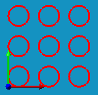
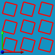
In these images you can see the Pattern CS in the bottom left corner. The "start hole" is directly adjoins the Pattern CS - immediately above the X-axis and immediately to the right of the Y-axis. The hole pattern will be determined starting from this hole.
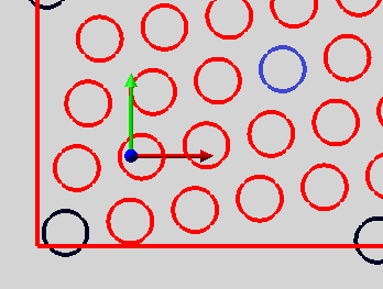
If the Flush checkbox has been deactivated, the "start hole" will be placed centrally in the origin of the coordinate system:
Excluded from this principle are Special holes that can be freely defined via sketches: If you have activated the Flush checkbox, you need to manually enter the X- and Y-offset of the sketch.
If you want to choose a different Pattern CS later, you can identify it after a click on the  button.
Processed area
The so-called "processed area" is the area of the part into which the hole patterns will be placed. This area can be defined in two different ways:
You can us a sketch that must meet the following requirements:
- It must be located on the XY-plane of the Pattern CS.
- It must have a closed polyline, i.e. without any gaps, and
- All edges of the sketch must be located within the limits of the part to be processed.
After a click on you can either define an existing sketch in the model drawing or a surface of the part as the processed area. If you choose a surface, you must also specify an additional Offset.
Alternatively, you can create and edit a new sketch in the plane of the installation coordinate system after clicking on using the New sketch in plane  function. The Process sketch
  function allows you to edit an already selected sketch afterwards.
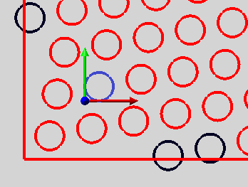
After defining the processed area, a preview of the hole pattern to be applied will be shown in the model drawing. Please note that only holes that stay in their entirety within the limits of the defined processed area will actually be applied:
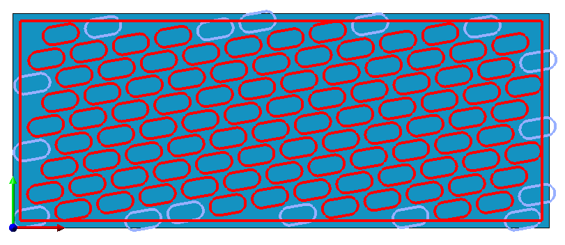
In the image above, the holes that are displayed in red will be applied - the ones that are displayed in the special colour Marking 2 are partly outside the processed area and will therefore be ignored.
Offset
![]() Please note:
Please note:
This function is only available if you have selected a surface has been processed area.
The processed area must lie entirely in the limits of the part to be processed, that is, even the borders of the part are considered as "outside the part". Therefore you need to define an offset to meet all requirements for the processing if you want to apply it to a part surface. The offset defines the distance between the border of the surface and the processed area.
Omitted area
The so-called "omitted area" is, like the "processed area", defined by a sketch. No holes will be applied to the omitted area.
To define an omitted area, activate this function  . If you click on the checkmark, it will disappear, deactivating the function again.
For a sketch defining an omitted area, the same rules as the ones for the definition of a processed area apply, with the difference that all edges of the sketch must lie within the limits of the part to be processed.
To select a sketch for the definition of an omitted area you use the same function as the one for the processed area.
Border mode
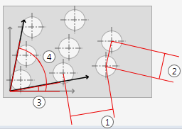
You can specify how to handle holes that cut the border of the processed area and are therefore only partially inside the processed area. The Border mode option is available for this purpose. The possible options are:
- No hole on border: Only holes are created that lie completely within the processed area.
- Complete hole on border: Every hole that lies partly or completely within the processed area is created completely.
- Intersect hole with border: Holes that lie only partially within the processed area are only partially created.
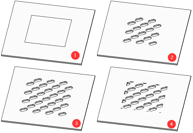
(1) Template: Hole with area to be processed; (2) No hole on border; (3) Complete hole on border; (4) Intersect hole with border
Use catalogue
For the actual description of the hole pattern you have two options: You can either define a hole pattern yourself, or use a readily defined hole pattern from the catalogue. The catalogue offers hole pre-defined patterns according to DIN for selection.
Activate the Use catalogue checkbox if you want to use hole patterns from the catalogue. This activates the selection field for a catalogue entry, while the areas for definition of own hole patterns are deactivated. Click on the  button to open the catalogue and select the desired hole pattern.
If you prefer using self-defined hole patterns, deactivate the Use catalogue checkbox and use the Process and Pattern areas to define your own hole patterns.
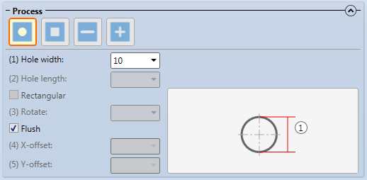
Process
![]() Please note:
Please note:
This area is only available if you have deactivated the Use catalogue checkbox.
You can choose between different hole shapes, for which different parameters are available. The parameters are explained further down.
|
|
Creates circular holes. Parameters: Hole width. |
|
|
Creates quadratic, square holes. Parameters: Hole width; if you use the Freely staggered rows option, also a rotation angle. |
|
|
Creates slots that can be rectangular or filleted at their ends. Parameters: Hole width; Hole length; Rectangular or non-rectangular (i.e. filleted) slot; if you use the use the Freely staggered rows option, also a rotation angle. This hole variant cannot be selected in combination with the Diagonally staggered rows option. |
|
|
When you choose this option, you can select a sketch serving as a template for the holes. This sketch must have a closed polyline (i.e. without gaps) which must not contain any further lines. After a click on the After selecting a sketch, you can process it by clicking on the arrow symbol Parameters (only if the hole pattern Freely staggered rows is used): An angle about which the hole is rotated; an X- and Y-offset. |
 next to the button to choose the
 Parameters
Only those parameters that are possible in combination with the chosen hole shapes and hole patterns will be active. Available are:
|
Hole width |
Specifies the width of the hole. This parameter is not available for special holes. |
|
Hole length |
Specifies the length of a hole. This parameter is only available for slots. |
|
Rectangular |
Specifies whether slots have rectangular or filleted ends. This parameter is only available for slots. |
|
Flush |
Determines whether the start hole id placed flush (activated) or centrally in the origin of the Pattern CS (deactivated). |
|
Rotate |
Rotates the hole about its centre by the specified value. This parameter is only available for freely staggered rows; it is not available for round holes. |
|
X-offset and Y-offset |
The X-and Y-offset are only available for special holes. Its effect is that the pattern is moved by the specified values in X- and Y-direction of the Pattern CS. |
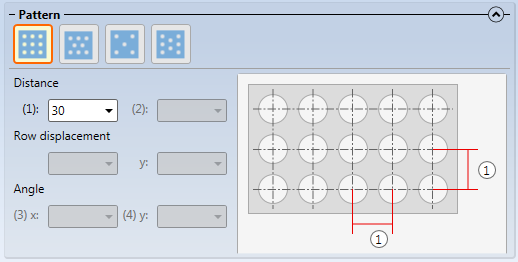
Pattern
![]() Please note:
Please note:
This area is only available if the Use catalogue checkbox has been activated.
Here you can choose between different patterns, for which different parameters are available. The parameters are explained further down.
|
|
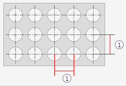
The holes are arranged on a quadratic grid (the angle between X- and Y-axis is 90 degrees).
Parameters: Distance of holes in X- and Y-direction. |
|
|
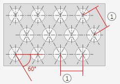
The holes are arranged on a grid in which the angle between the Y-axis and the X-axis is 60 degrees, so that the three neighbouring holes form an equilateral triangle.
Parameters: The distances of bores to each other and one row displacement. |
|
|
The holes are arranged on a grid in which the angle between the Y-axis and the X-axis is 45 degrees, so that the three neighbouring holes form an isosceles triangle. In addition, the holes are rotated 45 degrees.
Parameters: The distances of bores to each other and one row displacement. |
|
|
The grid for the holes can be freely defined here.
Parameters: All parameters are available. |
Parameters
Only those parameters which can actually be used for the selected patterns will be active. Available are:
|
Distance or |
This value determines the distance of the holes to each other. For Straight rows, Staggered rows and Diagonally staggered rows you can only define one distance.For Freely staggered rows you need to define a distance in X-direction and a distance in Y-direction. |
|
Row displacement or |
For Staggered rows and Diagonally staggered rows only one row displacement can be defined; for Freely staggered rows, row displacements in X-direction and Y-direction are available; for Straight rows no row displacement is possible, since it has no influence on this type of pattern. Further information will be provided in the Row displacement paragraph below. |
|
X-angle and Y-angle |
These parameters are only available for Freely staggered rows. They determine the angles of the two axes of the hole pattern in relation to the X-axis. Straight rows have angles of 0 and 90 degrees, Staggered rows have 0 and 60 degrees, Diagonally staggered rows have angles of 0 and 45 degrees. |
Row displacement
The setting option Row displacement allows you to move the grid of the holes by an arbitrary number of rows and columns. In the process, HiCAD moves the start hole by the specified number of columns and/or rows.
Example: A round hole in a freely staggered pattern with angles of 10 and 70 degrees. The start hole has been highlighted in blue:
An X-row displacement of 1 leads to the following result:
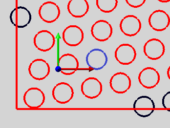
As you can see, the start hole has been moved by 1 position along the X-axis.
Likewise, an X-row displacement of 2 leads to the following result:
In additon, an Y-row displacement can be performed. With an X-row displacement of 2 and an Y-row displacement of 1 you obtain the following result:
In cases where the axes of the patterns lie on one of the axes of the Pattern CS, a displacement along this axis will have no effect on the result. Therefore, no displacements are possible for Straight rows patterns, and for the patterns Staggered rows and Diagonally staggered rows displacements are only possible along one axis.
A concrete example of a row displacement:
Staggered rows pattern, first without row displacement, then with a row displacement of 1.
This example demonstrates that a row displacement of 2 would again produce the same result here as a row displacement of 0.
Feature log entry
The Hole pattern function creates a same-named Feature log entry:
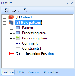
Double-clicking this entry will open the filled in Hole pattern, dialogue window, enabling you to make subsequent changes to this hole pattern.
Example
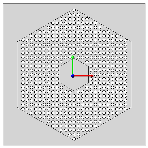
In this example a straight hole pattern was applied to quadratic plate. The processed area is a hexagon; in addition, a hexagonal omitted (i.e. unprocessed) area has been defined. The pattern CS is located in the bottom left corner of the plate:
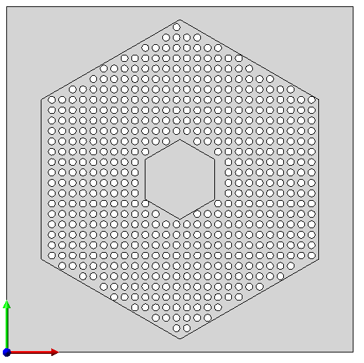
As you can see, the hole pattern has not been placed symmetrically in the processed area. Even a moving of the Pattern CS to the centre point of the hexagons does not produce the desired result:
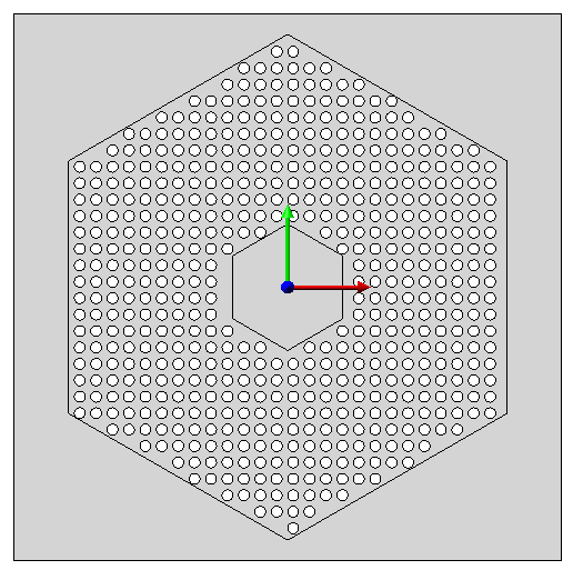
The reason for this is that, due to the active Flush checkbox (=default), the hole pattern is spread out from a start hole that is located to the right and above the Pattern CS (see Pattern coordinate system paragraph).
One possibility to achieve the desired goal is to deactivate the Flush checkbox to place the start hole in a centred position.
A possible alternative to this would be the moving of the Pattern CS.
To place the start hole exactly in a centred position, the Pattern CS must be located directly to the left and below the hole. If the hole width is 10 mm, it must be located 5 mm to the left and 5 mm below the centre point of the hexagon.
With the help of the point options R and M, the Pattern CS can be placed accordingly: