Drawing Derivation
Drawing > Itemisation/Detailing > Drawing derivation 
As of Version 2012 the drawing derivation functionality has been expanded to a function for general drawing derivation, which can now also be applied to general parts, e.g. mechanical engineering parts. The function can be found, just as the function for itemisation and detail drawing creation, on the Drawing tab.
Clearly arranged, well-structured technical drawings, e.g. workshop , overall, production or detail drawings drawings are absolutely essential to a safe and reliable planning and production. The automatic, optimised generation and management of these important documents in HiCAD is based on state-of-the-art technologies and ensures - even when dealing with very complex constructions - a rapid generation of the required production documents, including production-oriented dimensionings and annotations.HiCAD automatically detects the required number of parts for detail drawing creation and distributes the production views on the drawings according to practice-oriented logics.

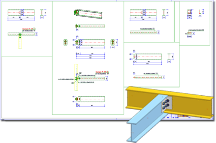
Example of a workshop drawing (bottom right: original model)
Automatic drawing derivation - An overview of functions and options:
- Powerful functionalities for the creation and management of drawings
- Management of all detail views in one view group - with view-comprehensive parameters
- Automatic, collision-free and space-saving arrangement of views and view groups, item numbers, annotations, dimensions etc.
- Alignment of views according to fitting position and perpendicular to sections
- Automatic spreading of production views over several drawing sheets with drawing frames
- Automatic, collision-free annotation of parts
- Automatic integration of assembly-BOMs into workshop drawings
- Integrated drawing creation for sheet metal parts, general 3-D parts and assemblies
- Creation of dimensioned sectional views for welded-on parts
- Depth limitations for sectional and detail views
- Individual views, sections and details
- Individually configured dimensionings and annotations
- Displayable grid axes and associative axis annotations
- Displayable part environment with flexibly configurable representation parameters
- Individually configurable dimensioning rules for each dimension in the drawing
- Usage-dependent configurations (e.g. for beams, girders, transoms, railings etc.)
- Shaded views in the workshop drawing
- Extensive reworking and supplementing options for the drawings
 Important:
If you use a Steel Engineering suite or a Steel Engineering module in conjunction with HELiOS Engineer, please read the information given in the Management + BIM Online Help!

