Project: HiCAD Sheet Metal
Sheet Metal > Process > Coating
Use the Coating function to define the coating description, the coating colour (RAL, NCS, system and drawing colours) and the coating type (outer side, inner side, edge) of a Sheet Metal main part.
The coating description and the coating type are taken over into the part attributes mask and are then also available in BOMs.

Areas of the input mask:

For sheet selection you can choose between the following two options:
|
|
With this option, a preview (in shaded mode) of the coating is displayed after selecting the outside of the sheet, provided that you have not activated any options that require further specifications. If the Apply immediately option is active, the coating parameters are applied immediately if they are entered correctly and you can select the outside of a new Sheet Metal part. Changes are then made via the feature log. If you want to change the surface after identification, use the If you are working in shaded mode, you will see the coating in the selected colour. |
|
|
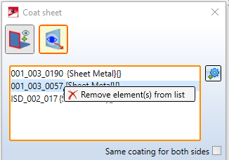
If you have already assigned a visible side to sheets using the Determine visible side function, you can now select these sheet parts. A multiple selection is also possible.
Right-click on a Sheet Metal part to remove it from the list. If you want to select more sheets, select the |
For colour display you can choose between system colours and drawing colours, or the Catalogue colours  RAL and NCS.
In the part attributes the type and the description of the coating are displayed. To view the part attributes, right-click the Sheet Metal main part in the ICN and choose Properties > Part attributes.
The following coating types are composed of the surfaces of the Sheet Metal part. You can choose between:
If you activate the Same coating for both sides checkbox, only one parameter box will be shown instead of the two ones for outer side and inner side. The entered values will be applied to both sides.

You can select a RAL or NCS colour from the catalogue or a system colour as the coating colour. Activate and click the icon to display a selection list with the RAL or NCS colours. Otherwise, you can pick a system or drawing colour from the Colour selection box.
If you have selected a catalogue colour, you can also take the description from the catalogue  . The description will be taken over into the part attributes mask.
|
RAL |
RAL colours are standardized colours that were created and are managed by the RAL gGmbH. They represent globally used colour systems and colour catalogues, each comprising a standardized colour palette (digital and printed). Each colour has a unique number, which allows a clear and unmistakeable communication of colours, e.g. for paints, without having to submit a colour sample. |
|
NCS |
The Natural Colour System (NCS) is a standardized colour system based on the human perception of colours. Currently it comprises 1950 colours that are arranged logically according to their tone and saturation. All colours that are listed in the NCS system as theoretical values can also be created in practice. They are designated by means of a combination of numbers and letters. |
|
System colours |
System colours are surface and edge colours that are loaded with the current HiCAD system settings. They may vary on different computers. |
|
Drawing colours |
Drawing colours are saved with the drawing, i.e. directly in the .SZA file. In this way, drawings can also be represented in exact colours on different computers (e.g. computers of other users or customers). |
Use the 
 icons to copy, for instance, the parameters of the outer side to the inner side and vice versa.
You can display the front surfaces in the colour of the outer side or inner side, respectively. This setting will be taken over into the part attributes mask.
After entering all required data you can assign the coating to the part. If you click Apply, the coating will be applied, while the dialogue window remains open, enabling you to change the data, or apply them to another part. If you click OK, the coating will be applied and the dialogue window will be closed. If you click Cancel, the specified data will be discarded and the dialogue window will be closed. If you have activated the Apply immediately checkbox, the data will be directly applied.
 Please note:
If inputs are incorrect or missing, this will be indicated by the  symbol. If you move the cursor over the symbol, an explanatory text will be shown.

If the function cannot be executed with the currently entered data, a  symbol will be displayed on the OK button. If you move the cursor over the symbol, an explanatory text will be shown.

Sheet Metal part - Example:

(1) Surface on the outer side
(2) Outer side
(3) Inner side
(4) Front surface like outer side
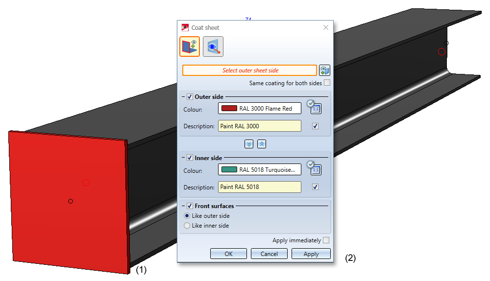
Steel Engineering plate - Example:
(1) Steel Engineering plate
(2) Coating settings
![]() Please note:
Please note:
If you activate the automatic development instead of the base sheet for a development, the side with the processing direction symbol will be developed. If the Sheet Metal part has no processing direction, the coated side will be developed.

|
© Copyright 1994-2020, ISD Software und Systeme GmbH |
Data protection • Terms and Conditions • Cookies • Contact • Legal notes and Disclaimer

 icon for identification.