Project: HiCAD Sheet Metal
Sheet Metal > Bend zone > Insert
With this function you can connect the flanges of a sheet metal part to a bend zone. The sheets are shortened so that the height or length does not change. The amount of the shortening depends on the bend radius.
The length of the bend zone can be determined by 2 points.
If the sheet width is different you can make a cut. The width of the sheet on which the attachment is made is retained.
The Insert bend zone function is recorded in the feature log and can be edited there afterwards.
After calling the function, the following dialogue window appears:

The areas of the input masks are:

Identify the connecting edge of the front side of each flange. Afterwards a preview will be shown if the input values make sense. If the option Apply immediately is active, the new bend zone will be added. Changes are then made via the feature log.
If you want to identify a different edge, click on the  icon for identifying the edge in the Connecting edges area.
![]() Please note:
Please note:
You can also select hidden edges in shaded views.
During data entry, you can cancel the function with the middle mouse button if no preview is displayed yet. Otherwise you can accept the preview with the middle mouse button. With the right mouse button you get further options.
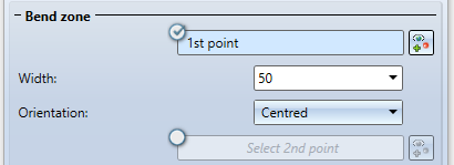
By activating the option for the 1st point  , the width of the new bend zone can be freely selected, independent of the connecting edge.
If you have selected the 1st point in the drawing, you can set the width and the orientation of the width, alternatively you can identify a 2nd point.
If you want to change the point selection, click on the  icon for identification.
If the relief groove is active, the installation mode is only taken into account in the area of the tab. If the relief groove is deactivated, the fitting mode (e.g. With shortening of the connecting flange) refers to the entire connecting edge.
Composite sheets, such as ALUCOBOND®, are formed using the milling edge technique. The resulting bend zones deviate geometrically from the cylindrical bend zones. For this reason, HiCAD gives you the option of selecting milling edge zones in addition to bend zones.

The following modes are available:
|
|
Bend zone The bend zone has the set bend radius. |
|
|
|
Milling edge zone Bend zone with the selected tool (milled inside). |
|
|
|
Milling edge zone, inverted Bend zone with the selected tool (milled on the outside). |
|
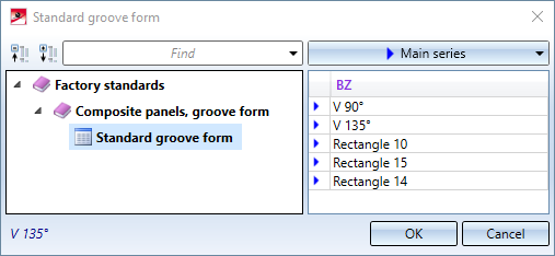
For milling edge zones you can click on the  icon next to the Groove form input field and choose a milling tool from the catalogue Factory standards > Composite panels, groove form > Standard groove form.
The bend radius is on the inside of the bend zone. If you right-click in the input field, you can pick the radius from the drawing.
If the checkbox for the Bend radius is active ![]() and the flanges have a semi-finished product assigned, the radius is loaded from the catalogue.
and the flanges have a semi-finished product assigned, the radius is loaded from the catalogue.
To obtain the blank (development) of the modelled sheet metal part, HiCAD offers you the development according to different allowance methods, which take into account the material-dependent length change of the workpiece, which occurs during bending. For this purpose HiCAD offers the empirical allowance methods that are also common in practice.
A calculation method is represented by a system file. These files are prepared exemplarily, but in practice each user will store one or more methods in this way. Before the installation you can select a system file here.
If the checkbox for the Allowance method is active and a semi-finished product is assigned to the flanges, the allowance method is loaded from the catalogue.
A clearance is created when you attach a sheet to the base sheet between 2 points and the connection area must be shortened due to the position. If you activate the right mouse button in the input field, you can pick the clearance from the drawing.
If the flange is smaller than the connecting edge and the fitting mode shortens the connecting plate, it is useful to install a relief groove. Specify the width, depth and type.

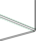
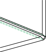
(1) Bend zone with relief groove
(2) Bend zone with clearance
(3) Bend zone with shortened flange, without relief groove
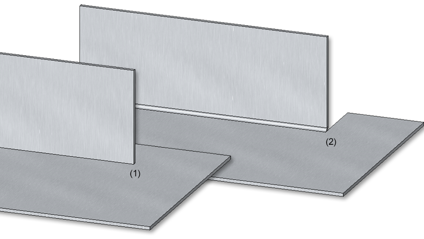
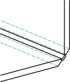
(1) Original situation
(2) Different flange widths with cut and clearance
Once you have entered all the necessary data, the new bend zone can be installed. If you select Apply or press the middle mouse button (MMT), the bend zone will be inserted, but the dialogue window remains open- in contrast to OK. This also allows you to change the data and assign it to another sheet metal part using Apply. If you close the dialogue window with Cancel, the function will be aborted without any insertion or modification taking place. If you have activated the  Apply immediately checkbox, the data will be applied directly.
![]() Please note:
Please note:
Incorrect entries are marked with this symbol  . Move the cursor over the symbol to display the error message.

If the function cannot be executed with the entered data, this symbol  appears on the OK button . Move the cursor over the symbol to display the error message.


Overview of Functions (3-D SM) • General Notes on Sheet Metal Processing (3-S SM)
|
© Copyright 1994-2020, ISD Software und Systeme GmbH |
Data protection • Terms and Conditions • Cookies • Contact • Legal notes and Disclaimer