Subtract, via Translation
3-D Standard > Process with sketch > SubtTra 
You use this function to insert a material subtraction into the active part. The bore is based on a sketch, which penetrates the active 3-D part in all its depth. The part that is created during subtraction is the difference between the active 3-D part and the extruded solid derived from the sketch.
To create a bore, proceed as follows:
- Activate the
Subtract tab and select Subtract with translation,
through
 as cross-section motion.
 - Activate the Include sub-parts checkbox if you want the sub-parts of the active part to be taken into account for the subtraction.
- If you want the subtraction to be created with adraught, enter the angle of inclination. The position of the form-inclination is influenced by the plus/minus sign.
- If you want to
use an existing sketch, click the Select sketch
 button and identify the sketch.
To create a new sketch, click the New sketch button. HiCAD displays the Sketch tab.
Create the desired sketch.
 - Define the other options by activating/deactivating the checkboxes.
- Click the Preview button to display the result.
- Click Apply if you want to apply the bore as displayed in the preview.

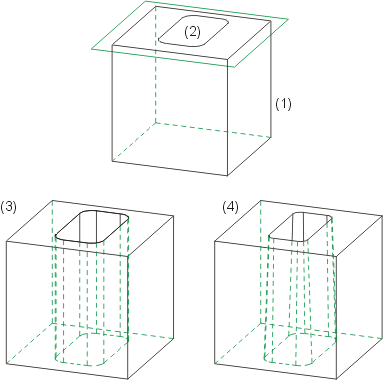
(1), (2) Cuboid with sketch (3) Bore, (4) Bore with draught (form-inclination)

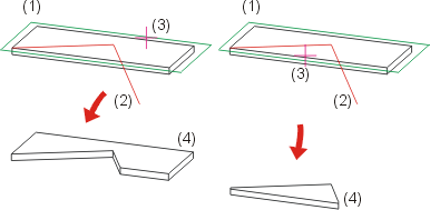
(1) Original part, (2) Open sketch, (3) Side to be cropped, (4) Result

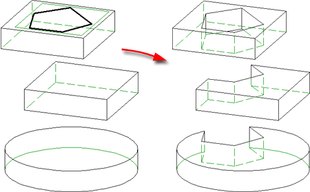
Left: Sketch, multiple selection; Right: Result
Click  to open a menu with further functions for the creation of subtractions or part divisions:

|
Subtract part, with translation + depth |

|
Delete subtraction |

|
Divide |
![]() Please note:
Please note:
- The name of the 3-D part is retained as the part name. If the sketch projects beyond the bounding edges of the 3-D part, it is cropped or, in the least favourable case, sliced. If the sketch completely overlaps the 3-D part, a dummy part is created.
- The direction in which subtractions and additions are applied depends on the current sketch plane.

"Process with Sketch" Dialogue Window (3-D) • Working with Sketches (3-D)
