 (Main part)
Project: HiCAD Sheet Metal
Sheet Metal > New > New sheet along sketch (Main part)
Sheet Metal > New > AlongSkt  > Sub-part
Use the New sheet along sketch function to create a sheet from a drawn sketch, taking parameters such as bend radius, sheet thickness and sheet depth into account. Depending on the selected function, the sheet will be created as a main part or a sub-part. To create a sub-part, you need to create a main assembly or a normal assembly beforehand. After activating the assembly and calling the function, the base sheet will become a sub-part of the assembly.
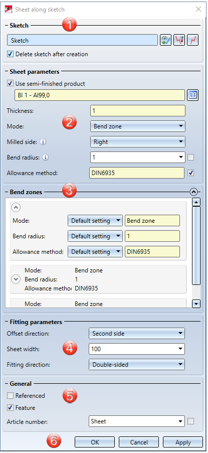
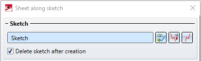
1. Sketch
3. Bend zones / Milling edge zones
5. General
6. Apply or discard value inputs

If a sketch is active in your drawing, this sketch will be automatically chosen for the creation of the new sheet. If there are several sketches, you need to select the sketch from which you wish to create the sheet.
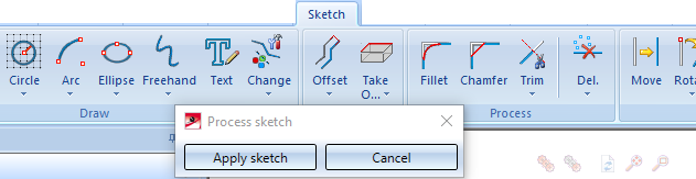
You can choose the  New sketch in plane function in the dialogue, and then draw a new sketch with the Draw functions on the Sketch tab. Then, leave the sketch mode by clicking on Apply sketch.
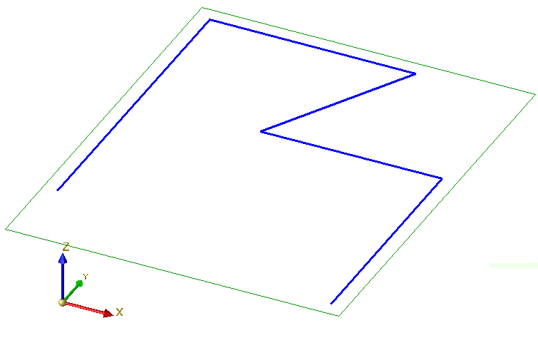
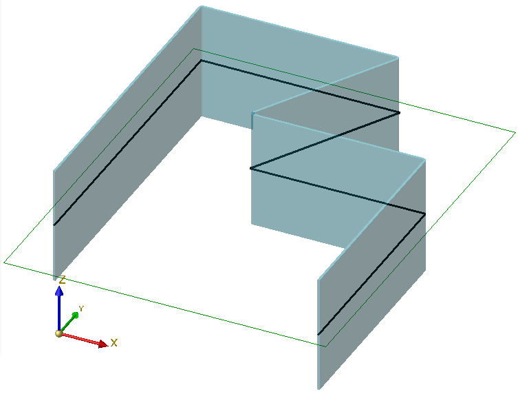
After identifiying the sketch, a preview of the new sheet will be displayed. If you want to identify a different sketch, click the  icon in the Sketch area and identify the desired sketch.
To modify the sketch click the  Process sketch icon. The Sketch tab and the Process sketch dialogue will then be displayed. Change the sketch and confirm with Apply sketch. The Sheet along sketch dialogue will then be displayed again.
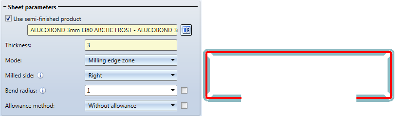
If you activate the Use semi-finished product ![]() , a semi-finished product will be chosen from the Catalogue Editor, and no value input for sheet thickness will be required; instead, the Sheet thickness, the Material and, if desired, the Article number will be taken from the Catalogue Editor.In the General area you have the option to change the article number even if a semi-finished product has been selected. If you also want to take the bend radius from the Catalogue Editor, activate the
, a semi-finished product will be chosen from the Catalogue Editor, and no value input for sheet thickness will be required; instead, the Sheet thickness, the Material and, if desired, the Article number will be taken from the Catalogue Editor.In the General area you have the option to change the article number even if a semi-finished product has been selected. If you also want to take the bend radius from the Catalogue Editor, activate the ![]() From semi-finished product checkbox beside the input field for the bend radius. In the Bend zones area the bend radius can even be changed if the
From semi-finished product checkbox beside the input field for the bend radius. In the Bend zones area the bend radius can even be changed if the ![]() From semi-finished product checkbox has been activated.
From semi-finished product checkbox has been activated.
For the Mode field you can choose between bend zone and milling edge zone. In practice, the milling edge zone is used for composite panels. For the Milled side which is only evaluated for milling edge zones the direction of the sketch is decisive. The setting will be used as the pre-setting for the entire Sheet Metal part and can be changed, for each milling edge zone, in the Bend zones area or via the Feature.
To preserve the blank (development) of the modelled Sheet Metal part, HiCAD offers various developments according to different, common allowance methods that consider material-dependent length changes of workpieces during bending processes. Each allowance method is represented by a corresponding system file. These files have been prepared appropriately; in practice, however, users may want to store their own allowance methods in this way. Activate the ![]() From semi-finished product checkbox beside the input field for the allowance method if you want to take the file from the Catalogue Editor.
From semi-finished product checkbox beside the input field for the allowance method if you want to take the file from the Catalogue Editor.
Semi-finished products can also be activated/deactivated or changed subsequently. To do this, double-click the Sheet along sketch feature. The dialogue window for sheet creation will be displayed, where you can activate or deactivate the checkboxes for semi-finished products, or select a different semi-finished product by clicking the  icon. Confirm with OK to apply the changes.
If you want to change the radius or the allowance method for a bend zone, expand the Bend zones area by clicking on the  icon.
icon.
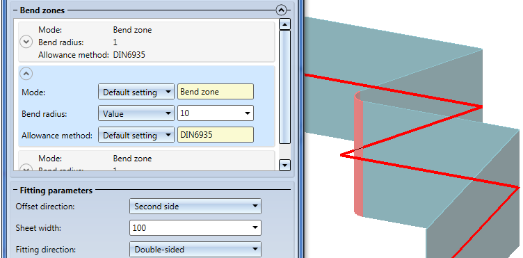
In the displayed table you can assign a value for the Bend radius and the Allowance method to each bend zone. Right-click  to equalize the values in a column.
For milling edge zones you can choose a tool from the catalogue, change the milling side and the mode.
The input will be immediately visualized in a preview.
Frequently used parts should be saved as referenced parts. The part will then be additionally stored as an individual part at the end of the function process, and will not exist as a fixed part in the drawing. When applying changes to the individual part, you can update the part in the drawing afterwards.
Remove the checkmark from the Feature checkbox ![]() to deactivate the features during creation of the sheet. The checkbox is active
to deactivate the features during creation of the sheet. The checkbox is active ![]() by default.
by default.
The name of the sheet will be automatically generated. You can overwrite it in the text field if the Semi-finished product checkbox has not been activated.
If the Via catalogue checkbox beside Article No. has been activated ![]() while the Use semi-finished product checkbox is also active
while the Use semi-finished product checkbox is also active ![]() , the article number will be loaded from the catalogue. If the Via catalogue checkbox beside Article No. has been deactivated
, the article number will be loaded from the catalogue. If the Via catalogue checkbox beside Article No. has been deactivated ![]() you can enter any article number.
you can enter any article number.
After completion of your data input you can create the new sheet. If you click Apply or press the MMB, the sheet will be inserted, and the dialogue window will remain open, allowing you to change the data and apply them to a different sketch if desired. Clicking OK inserts the sheets and closes the dialogue window. Clicking Cancel discards your value inputs and changes, without inserting the sheet.
 Please note:
Incorrect inputs are marked with the  symbol. If you move the cursor over the symbol, an error message will be displayed.

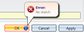
If the function cannot be executed with the entered data, the  symbol will appear next to the OK button. Move the cursor over the symbol to display an error message.
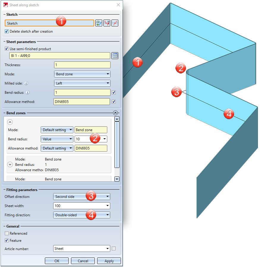
(1) Sketch
(2) Bend radius changed
(3) Offset direction
(4) Fitting direction
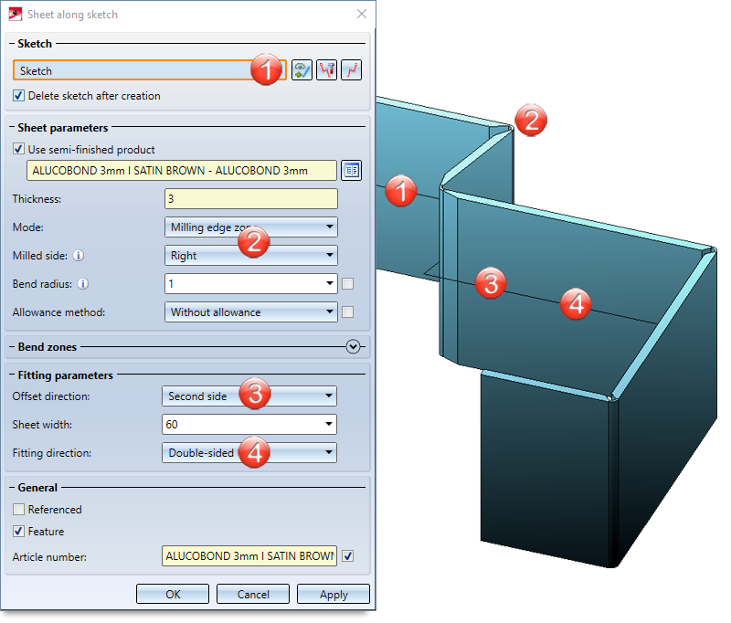
(1) Sketch
(2) Mode: Milling edge zone; Milled side: Right
(3) Offset direction
(4) Fitting direction
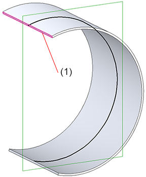
(1) Tangentially connected flange, 0,002 mm

|
© Copyright 1994-2020, ISD Software und Systeme GmbH |
Data protection • Terms and Conditions • Cookies • Contact • Legal notes and Disclaimer