Project: HiCAD Sheet Metal
Civil Engineering functions > Sheet Metal > Sheet Metal cassette
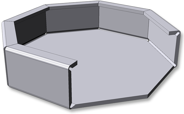
The Sheet Metal cassette Design Variant provides support during the construction of facades. Use this function to create rectangular or polygonal cassettes using Sketch technology.
Proceed as follows:
The Sheet Metal cassette dialogue window will be displayed.
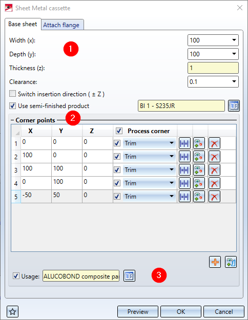
Base sheet tab
(1) Sheet parameters
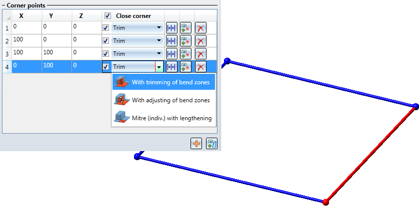
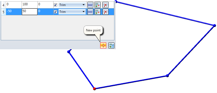
(2) Corner points
(3) Usage
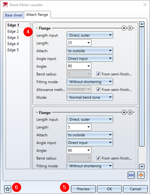
Attach flange tab
(4) Attach flange
(6) Favourites

You can change the shape of the base sheet in the Corner pointsarea of the dialogue window by adding further corner points  and/or changing the position. After clicking the
  icon you can identify a sketch as base sheet.
If you decide to Use a semi-finished product ![]() from the Catalogue Editor, the sheet thickness will not be queried. The Sheet thickness, the Material and the Article number of the sheet will then be taken from the Catalogue Editor. If you want to take the bend radius and the allowance method from the Catalogue Editor, too, open the Attach flange tab and activate the From semi-finished product
from the Catalogue Editor, the sheet thickness will not be queried. The Sheet thickness, the Material and the Article number of the sheet will then be taken from the Catalogue Editor. If you want to take the bend radius and the allowance method from the Catalogue Editor, too, open the Attach flange tab and activate the From semi-finished product ![]() checkbox for the Allowance method or Bend radius, respectively.
checkbox for the Allowance method or Bend radius, respectively.
Semi-finished products can also be activated/deactivated or changed. To do this, double-click the Sheet Metal cassette feature. In the dialogue window, activate or deactivate the Semi-finished product checkbox again, or click the  icon to choose a different semi-finished product. Confirm and close the window with OK.
The clearance is the distance between the flanges of the edges.
The active point will be highlighted in the drawing. Click on the drawing area to activate the Zoom functions on the transparent toolbar.
|
X, Y, Z |
The coordinates that you enter here determine the corner points of the cassette base sheet. |
|
Close corner |
The following functions are available for the closing of corners: Use these functions to mitre attached flanges (or sheets and bend zones, respectively) in one step. In the process, the bend zone will either be trimmed, adjusted or, if you choose Mitre (indiv.) with lengthening ignored. |
|
|
Applies the mitre setting to all corner points. |
|
|
Clicking this icon allows you to identify a corner point in the drawing. |
|
|
Deletes a corner point. |
|
|
Clicking this icon allows you to insert a new corner point. You can then enter the coordinates in the X,Y, Z input fields or determine the point in the drawing with the |
|
|
Clicking this icon allows you to apply a sketch as base sheet. |
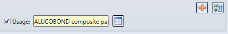
HiCAD supports part classification by freely definable usages. For instance, you have the option to define assemblies in Civil Engineering as Roof/Wall, Package, Roof etc.
Classification takes place here by assigning the attribute Usage to the cassette. Such classifications allow the creation of usage-dependent workshop drawings or BOMs. More, customer-specific usages can be added at any time with the help of the Catalogue Editor (CATEDITOR.EXE). The usages are managed in the Factory standards catalogue.
Further information on the Catalogue Editor can be found in the Online Help.
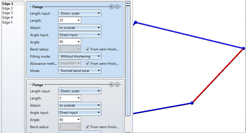
On the left hand side of the Attach flange tab you will find the numbered edges connecting the points you created on the Base sheet tab. The active edge will be highlighted in the drawing. Use the "Plus" icon to assign flanges to the edge. To copy the flanges to all other edges, click the Same for all corners  icon.
icon.
to assign one or several flanges to the edge. icon.
|
Here you enter the reference for the length. |
|
|
Length |
The length will be applied in consideration of the above reference. |
|
Attach |
Here you choose the direction of the flange. |
|
Here you enter the reference of the bend angle.
|
|
|
Angle |
The angle will be applied in consideration of the above reference. |
|
Bend radius |
The bend radius is located at the inner side of the bend zone. If a semi-finished product has been activated, the bend radius will always be taken from the Catalogue Editor. |
|
The fitting mode refers to the processing of the connecting flange. |
|
|
To retain the blank (development) of the modelled Sheet Metal part, HiCAD offers a development according to various calculation methods (allowance methods) that consider the material-dependent length changes of the workpiece that occur during the bending process. The allowance methods offered in HiCAD are the practice-oriented, empirical allowance methods. Activate the |
|
|
Composite sheets (e.g. ALUCOBOND® panels) are folded using milling edge techniques. The resulting bend zones deviate geometrically from the cylindrical bend zones. Therefore, you have now the option of selecting milling edge zones and inverted milling edge zones, in addition to bend zones. |
If you have entered all required data, you can create the new sheet.
If you click Preview, the cassette will be generated, and the dialogue window will remain open, allowing you to check and, if required, modify the result. If you click OK, the cassette will be generated, but the window will be closed. Click Cancel to close the window without generating the cassette.
If you have not created an assembly yet, you will now be prompted to do so.
If you want to apply the origin, you can do so with a right-click.
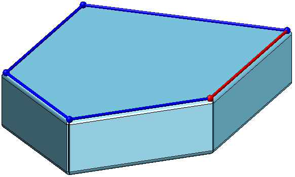
Cassette with bend zone
Cassette with milling edge zone

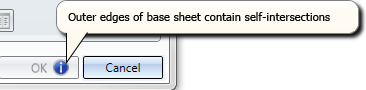
If the function cannot be executed with the entered data, this symbol  will appear at the OK button. Move the cursor over the symbol to . display the error message and see which value inputs were incorrect/missing.
The settings of the dialogue window can be saved as favourites and re-used at any time. To do this, click the  symbol at the bottom left of the window.
More information on favourites management can be found in the Manage Favourites topic of the HiCAD Basics help.

Sheet Metal Design Variants (3-D SM)
|
© Copyright 1994-2020, ISD Software und Systeme GmbH |
Data protection • Terms and Conditions • Cookies • Contact • Legal notes and Disclaimer


