> Individual
Project: HiCAD Sheet Metal
Sheet Metal > Sheet development > Update > Individual
Sheet Metal > Sheet development > Update > All 
Sheet Metal > Sheet development > Update > Default setting 
Use these functions to specify the development parameters for the 3-D developments created with the Develop sheet function. Depending on the selected function, you can change:
![]() Please note:
Please note:
The default setting for the sheet development and the changing of the Favourites also affects drawing derivations  for sheets, the export of developed sheets as DXF files
  and the settings in the Configuration Editor (Sheet Metal> Sheet development > Default setting).
In a drawing you can derive several developments with different parameter settings from one Sheet Metal part. The parameter settings will be saved in the development. In this way it is possible to save developments intended for DXF export, e.g. for LVD or Bystronic, with their different parameters in one drawing. After changing the Sheet Metal part, the different parameters will be taken into account when updating the development accordingly. Also, a new view will be created for each development.
The pre-setting for new drawings can be specified in the Configuration Editor at Sheet Metal > Sheet development > Default setting.
When you call the function, the following dialogue window will be displayed:


Here you specify the pre-settings for the option Sheet alignment: Automatic.
The options for the selection of direction and upper side (Direction symbol, Coated side, ...) can be changed by activating or deactivating the corresponding checkboxes  . The priority results from the ascending order of the active options.
If the Visible side option has been activated, the side chosen with the Determine visible side  will be made the upper side of the development.
For instance, the direction symbol marks the processing direction and the processed side with a direction arrow. In this way, the development will be created from the side on which the arrow is located, and will be automatically aligned horizontally to the direction symbol.
When milling composite panels the coated side is normally located at the bottom. Use the Invert upper side option to flip the upper side to the bottom.
The Bend lines and Bend zones beneath Representation can be activated or deactivated. Length, distance to outer contour, line type and colour can be specified in the Extended settings  on the Bend lines tab. Positive and negative bend lines can be configured separately.
Activate the Subordinate parts checkbox if you also want to show parts that are subordinated to a flange (e.g. welded nuts, 3-D parts).

Bend line and bend zone active
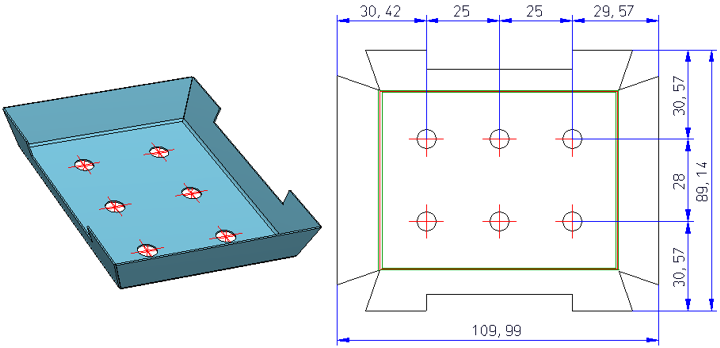
Isolated 3-D points of the Sheet Metal part can also be hidden or shown. The position of the points (in the development) refer to the flange or the bend zone that was active during creation. If the main part is active, no points will be developed.
The setting affects only the Isolated 3-D points  supplied by the Sheet Metal part. Isolated points in the development that have been created subsequently are always visible.

(1) Isolated point, (1a), active sheet flange
(2) Isolated point, (2a), active sheet flange
(3) Isolated point (3a), base sheet active
If you activate the Dimension checkbox, only the greatest extension in X- and Y-direction will be dimensioned.
If you activate the Outer contour checkbox, the complete contour will be dimensioned.
If you activate the Bend lines checkbox, the bend lines running parallel to the outer contour will be dimensioned, independent of the other dimensioning settings.
If you activate the Processings checkbox, dimension chains will also be created for bores and subtractions.
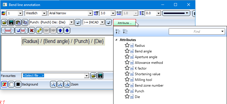
Here you can configure annotations for developments (bend lines, cross-breaks, punchings). Also, you can define additional texts, e.g. for the production. You can either define the texts manually, with the help of the Annotation Editor, or load the annotations for Bystronic or LVD via the Favourites  .
.
To start the Annotation Editor, click the  icon next to the option. For each annotation, the attributes for evaluation will be displayed. These can also be supplemented by additional, user-defined comments. You can assign to each text block the properties Font, Character set, Font size, Line spacing, Font colour, Aspect ratio/Inclination (only for HiCAD fonts) and the orientation of the text (left, centred, right).
|
Bend line texts |
Different attributes and text properties can be assigned for positive and negative angles. This icon If you want to display the angles, you can choose between Bend angle and Aperture angle. To show the allowance method or the milling tool in the development you need to activate the attribute in the Annotation Editor. The bend line and, if required, the bend zone, can also be represented by two short lines at the start and the end of the bend edge instead of one continuous line. The representation of the bend line can be defined in the Extended settings. |
|
Cross-break height, |
The cross-break height and the cross-break angle can be displayed in the development. |
|
Punching, moulding and embossing tools |
When you activate this option, the WZNR (Tool number) column from the catalogue will also be output with the development. |
|
Auxiliary text |
Use this option to create an additional text which will be evaluated by the software of the sheet metal processing machine (LVD or Bystronic). If you choose Positioning: Inside/Outside, the dimensionings, the article number and, in some cases, the item number will be displayed by default. The text will be generated from the part attributes. If you choose Text with leader line, the annotation will be placed in the form of a tag with a leader line. |
![]() Please note:
Please note:
If you move the cursor over a text in the 3-D development, the text will be highlighted in magenta. If you now press and hold down the left mouse button you can move the text. When you update the development the text will be moved back to its original position. If you move the bend line text along the bend line, the position will be preserved after carrying out an update.
The settings of the dialogue window can be saved as favourites and re-used at any time. To do this, click on the  symbol at the bottom left of the window.
The settings for LVD, Bystronic, COBUS NCAD and Lantek Expert have been predefined and saved as Favourites.
The Favourites delivered with the software are only examples and may require adjustment to your (LVD, Bystronic etc.) machines.
More information on Favourites Management can be found in the Manage Favourites topic of the HiCAD Basics Help.
Favourites can be loaded as default settings for new drawings in the Configuration Editor at Sheet Metal > Sheet development > Default setting.
The Extended settings dialogue window consists of the following tabs:

In the upper area of the dialogue you can specify the settings for the Line colour, Line type and Layer of the different edges.
For instance, you can specify the colour, line type and layer for powder marking lines here. If you deactivate the checkbox  here, the pre-set line parameters will be used.
You can assign different parameters to inner and outer contours. Inner contours are all contours that can be cut out of the sheet and are no standard processings. This allows you, for instance, to define the adjustment of the layers for the DXF export more accurately.
You can select different line parameters for positive and negative bend angles. For Start angle and End angle, respectively, you can specify an area of the angle for the line colour. Use the Plus icon  to add further rows for new angle areas. Use the Delete
  icon to delete a marked row.

The development of a sheet is always a 3-D part. To exclude cross-breaks, mouldings (including punches and bore patterns) or catalogue symbols from the 3-D representation, activate the corresponding checkbox .
![]() Please note:
Please note:
For sheets with agraffes, e.g. suspended ALUCOBOND® panels, the position of the agraffes will only be dimensioned in derived drawings if the Processings checkbox in the Sheet development default settings dialogue window has been activated. Agraffes will only be dimensioned if the Planar representation for mouldings checkbox in the Extended settings of this dialogue window has been deactivated. Start point and end point of the agraffe will be considered in the dimensioning of the outer contour.
the direction symbol for the processing direction was not visible in the DXF export if it was located on the rear side of the sheet development. On facade panels (e.g. ALUCOBOND® panels) the direction symbol is often located on the front side of the trays. The development will then be carried out from the rear side in order to display the milling edges. Here, too, the direction symbol would not be visible in the export.
To visualize the direction symbol on the other sheet side, choose Sheet development > Update> Default setting and then, in the opened dialogue window, click on the Extended settings icon. In the next dialogue window, open the Extended representation tab and activate the Always show direction symbol on both sheet sides checkbox to copy the symbol to the other side of the sheet.
Fillets exceeding the maximum radius will not be marked as bend zones.
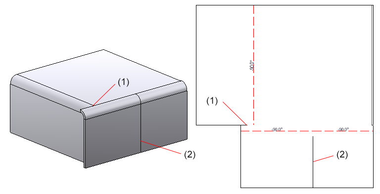
The Displayed as: selection list allows you to choose a preferred representation of the created development. The default value is Hidden Line.

(1) No planar representation
(2) Planar representation for cross-breaks and moulding
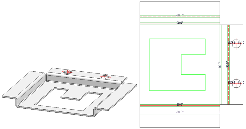
If two flanges abut when performing a development without clearance, a new line representing a separating cut will be inserted in the development. If the front surface of a bend zone directly abuts on a flange, here, too, a separating cut line will be inserted.
If you do not want to show separating cut lines between flanges, or between flanges and bend zones, deactivate the corresponding checkbox Extended representation tab.
(1) Separation cut line between flange and bend zone
(2) Separation cut line between flanges
Bend lines can also be represented as two short lines at the start and the end of a bend edge instead of one continuous line. Furthermore, you have the option to mark the start and the end by means of a punch. Here, too, you can specify different values for the positive and the negative angle.

This icon  copies the settings from the positive to the negative angle and vice versa.

The milling tool path will be displayed if you have activated Bend zone checkbox beneath Representation in the Sheet development default settings dialogue. The appearance of the tool path is determined on the Milling + Folding tab of the Extended settings dialogue window that you open with a click on the symbol.
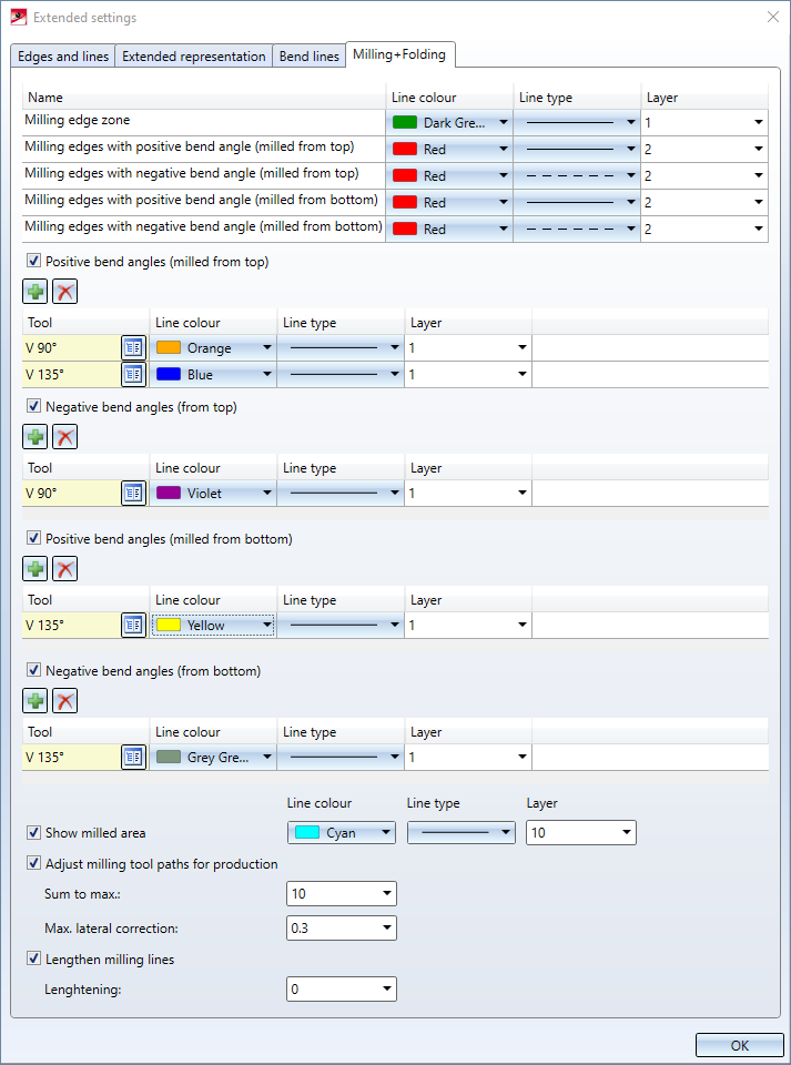
In the upper part of the dialogue you can specify the settings for Line colour, Line type and Layer of the different tool paths.
You can then specify tool-dependent line parameters for positive and negative bend angles; "milled from top" refers to the edge that you chose for Sheet alignment: Automatic (see above).
By the specification of tool-dependent settings the milling tool paths in the upper part of the dialogue may be overwritten.
The icon adds a row for a tool from the catalogue. Click the icon to delete a marked row again.

(1) Positive bend angle, milled from top, Tool V 135°
(2) Positive bend angle, milled from top, Tool V 90°
(3) Negative bend angle, milled from top, Tool V 90°
The bend line text was expanded by the Milling tool attribute by clicking the icon next to the corresponding option.
You use the Show milled area option to mark exclusions that you have defined, e.g., with the 3-D function Subtract part, via translation ![]() . For the triangular SZ-20 panel in Element Installation, too, the material in the "acute corner" will be excluded (milled away). The milled area will be recognized when creating the development. That is, facets which are no cover facets, which run parallel to the cover surface, and which have no standard processings form the milled (i.e. subtracted) area.
. For the triangular SZ-20 panel in Element Installation, too, the material in the "acute corner" will be excluded (milled away). The milled area will be recognized when creating the development. That is, facets which are no cover facets, which run parallel to the cover surface, and which have no standard processings form the milled (i.e. subtracted) area.
To prepare this area for machining, for machine control during DXF output, a layer must be defined for this milled area.

If you activate this option, the edges of the milled area will be entered in the development. The edges are sorted and oriented as specified for inner cycles. Milled areas are combined across milling edge zones.
The generation is activated in the development Favourite for Cobus NCAD: Color 10, Continuous line, Layer 10 In HCADACAD_COBUS.DAT the layer assignment MILLING is defined for the DXF export.

(1) Exclusion in Sheet Metal panel
(2) Exclusion in development (top view)
(3) Exclusion in development (Isometry)
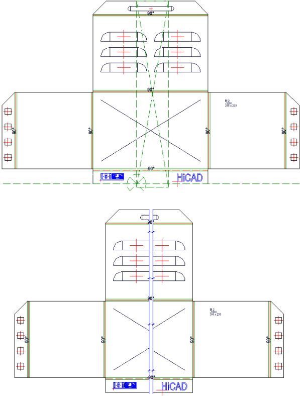
The Adjust milling tool paths for production option refers to sheet corners where three milling edge zones converge. In the development, the lines do normally not converge in a common intersection point.
Therefore you have now the option to adjust the milling lines in such a way that they end in one common point.
It is important that only the milling lines are adjusted, and not the 3-D geometry.
If there are two converging milling lines, the milling lines will be lengthened / shortened, so that they converge in a common intersection point.
For this purpose there are two parameters:
|
Sum to max. |
With this parameter you define corners in which several milling lines converge. The distance of the end points is pairwise smaller than the snap distance. |
|
Max.lateral correction |
This value defines the extent to which the new milling line may laterally deviate from the adjusted milling line. Decisive is the distance of the new end point to the original milling line. |
In order to fold Sheet Metal cassettes with milling edge zones better and more easily, the milling edge zones are often extended a little at the intersection points. You have the possibility for milling edge zones to extend the bend line on the Milling+Folding tab of the Extended settings dialogue window. There, activate the Lengthen milling lines checkbox and enter a value.
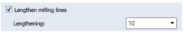

Lengthening of bend lines in the development
After confirming the settings with OK, the parameters will be applied, depending on the selected function (Individual, All or Default setting).
For the Individual function you have the option to display a Preview by clicking on the same-named button.
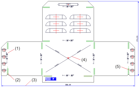
(1) Bend radius and bend angle with different annotation parameters
(2) Different colours for interrupted bend lines and bend zones
(3) Dimension
(4) Cross-break with red height and black angle
(5) Punch with tool number
In shortened views of sheet developments the bend zone texts will be preserved.

Overview of Functions (3-D SM) • General Notes on Sheet Metal Processing (3-D SM) • Development (3-D SM) • Create 3-D Development (3-D) • Process Development (3-D)
|
© Copyright 1994-2020, ISD Software und Systeme GmbH |
Data protection • Terms and Conditions • Cookies • Contact • Legal notes and Disclaimer