Sketch > Draw > Line 
The 3-D sketching tool is a comfortable tool for the creation of three dimensional lines. If a 3-D sketch is active, the 3-D sketching tool is started by calling the Line function.
The Sketching tool simplifies designing by the fact that HiCAD - starting from the last point of a polyline - automatically displays auxiliary lines along a predefined grid and - depending on the selected mode - displays the corresponding angles, distances or radii at the cursor. On this grid you can, for example, determine the direction and length of a line with a mouse click by moving the cursor accordingly. Since 3-D sketches - like other 3-D parts - have a part coordinate system, the plane in which they are drawn can be changed at will while drawing. This drawing plane is always parallel to the selected plane and runs through the last point determined.
The subjects of this topic are:
- Procedure
- Mode selection
- Grid and Angle reference
- Point options of the Autopilot
- Taking into account of Plant Engineering parts
Please also read the information given in the Entering HCM Constraints topic.

Procedure
- Create new 3-D sketch or activate existing 3-D sketch
You create a new 3-D sketch (this also defines the part coordinate system of the sketch) or you activate an existing 3-D sketch. - Start the 3-D sketching tool
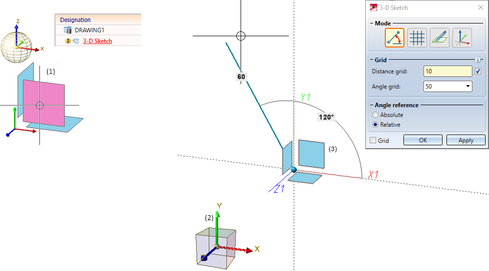
To draw a 3-D polyline with the 3-D sketching tool, activate the Line function. The 3-D Sketch dialogue window appears.
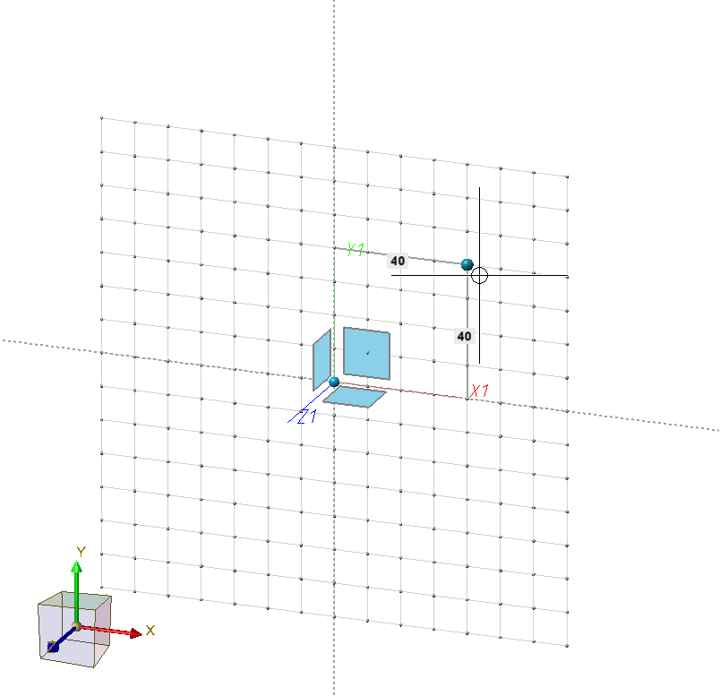
At the same time, a plane preview is displayed in the drawing, which represents the part coordinate system of the 3-D sketch. The current drawing plane when the sketching tool is called is the XY-plane of this coordinate system. The X- and Y- axes are shown as dashed auxiliary lines, and the point marked in blue represents the origin of the part coordinate system of the sketch.
An example:
Let's suppose you have created a new 3-D sketch and selected the default XY-plane (1). (2) shows the part coordinate system defined by it. If you then call the Line function, the displayed plane preview (3) is shown. After the call, the drawing plane is the XY-plane of the part coordinate system.
- Determine start point
In the info bar the following text is now displayed:
Select start point or plane (MMB = Cancel, RMTB= Further options)
You now have the following options:
- You determine the start point of the polyline. This can be done either by releasing the cursor, by taking over a point found with the Autopilot or with another point option. The drawing plane and the plane preview will be automatically moved to this point.
- You change the drawing plane by selecting a plane of the part coordinate system in the preview or a processing plane in the drawing.
Pressing the middle mouse button (MMB) cancels the sketching tool without creating a polyline.
 If the start point is defined with the point option Online on edge through point (O), then the relative grid is aligned to the line.
- Determine following points / Context menu
After you have selected the starting point of the polyline, determine the following points in the same way. In the info bar the following text is now displayed:
Select end point or plane (MMB = Cancel, RMB= Further options)
You can also change the drawing plane at any time.
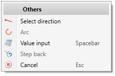
By pressing the middle mouse button you can start a new polyline (in the same 3-D sketch). By pressing the right mouse button, a context menu with further options can be activated.
|
Functions |
|
|---|---|
|
|
This function allows you to change the direction in which the next line is to be drawn. To do this, you define the direction vector by defining two points, by selecting a straight line or by selecting a surface. If a surface is selected, the direction is determined by the surface normal. |
|
|
This function allows you to insert arcs into the polyline. The starting point of the arc is always the last point. You can now draw an arc dynamically with the cursor. The arc radius and opening angle are displayed at the cursor. First select the radius of the arc. To do this, drag the arc so that the desired radius is displayed and drop the cursor. The direction in which the arc is drawn (tangential or non-tangential) depends on the click point when the function is selected. If you want to use a specific radius, press the space bar or select the function Value input and enter the arc radius. You determine the end point of the arc either by placing the cursor (the opening angle is displayed) or with a point option. If the last determined point is selected again, the drawing of an arc is automatically started.
|
|
|
If you want to enter a value, for example a length or a radius, explicitly via the keyboard, you can choose this function. HiCAD then displays the calculator and you can enter the desired value. Instead of calling the function, you can also simply press the spacebar while working with the sketching tool. |

|
Step back If you want to go back one or more input steps to correct the entry, choose the function Step back (several times if necessary). Alternatively, you can also use the Undo function during the function dialogue. |

|
Cancel (ESC) Cancels the function. |


- To complete your polyline, click either OK or Apply in the dialogue window. Clicking OK closes the dialogue window. If you choose Apply, the dialogue window remains open, allowing you to draw more polylines (for the same sketch).
|
An example of how to create a 3-D sketch with HCM constraints in a few steps, for example as the basis for a handrail bracket, can be found here . |
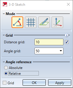
Mode selection
Use this area of the dialogue window to select the sketch mode. You can switch between sketch modes as you draw the polyline. The following modes are available:
|
|
Angle + Distance In this mode (default), the angle and distance to the last point are displayed at the cursor. To determine the next point, place the cursor at the desired position and copy it with the left mouse button. |
|
|
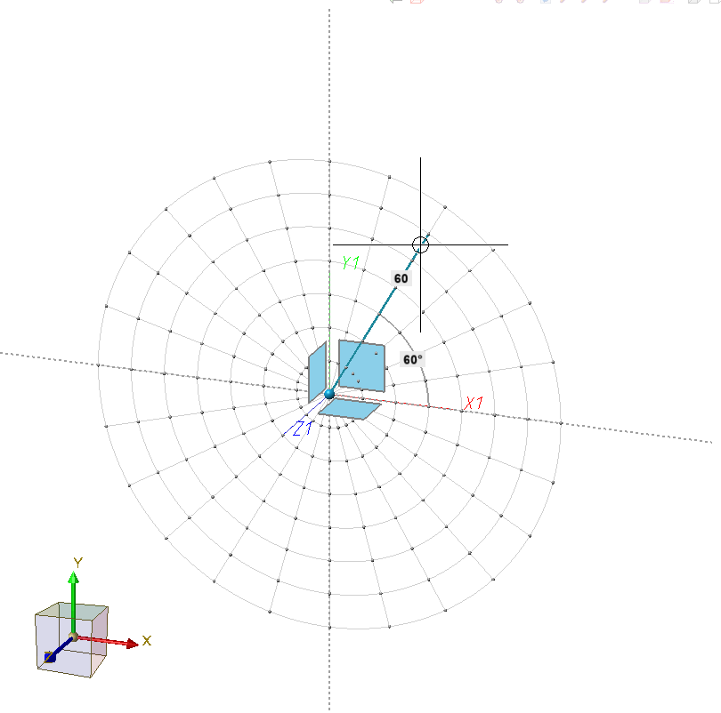
XY-grid The X- and Y-distances to the last point are displayed. To determine the next point, place the cursor at the desired position and accept it with the left mouse button. If the Grid checkbox at the bottom of the dialogue window is active, the following grid points and lines are displayed.
|
|
|
Free In this mode you can draw freely, i.e. without a grid. The X- and Y-distance to the last point are displayed at the cursor. To determine the next point, place the cursor at the required position and accept it with the left mouse button.
|
|
|
On axes In this mode you draw on the axes of the current coordinate system. The plane preview is hidden. If the Grid checkbox at the bottom of the dialogue window is active, grid points on the axes of the coordinate system are displayed as an aid |


|
Please note:
|
Grid and Angle reference
Under Grid you define the fineness of the distance and angle grid.
Alternatively, you can change the fineness of the grid while drawing using the keyboard:
|
Keys |
Effect |
|---|---|
|
+ and - |
Changes the fineness of the distance grid |
|
SHIFT+ and SHIFT- |
Changes the fineness of the amgle grid |
The Angle reference defines what the selected angle refers to:
|
Absolute |
Der Winkel bezieht sich auf die X-Achse des Teilekoordinatensystems. |
|
Relative |
Der Winkel bezieht sich auf die letzte Linie. |
If the checkbox next to the Distance grid field is active, the value for the distance grid is automatically adjusted when zooming the drawing . This is the default setting.
By activating the Grid checkbox - at the bottom of the dialogue window - grid points and lines can be displayed as an aid for determining angles and distances
Point options of the Autopilot
When sketching lines, additional options are available when using the Autopilot to determine points:
|
|
is displayed if the X-coordinate of the current cursor position is identical to the X-coordinate of another point in the active 3-D sketch. |
|
|
is displayed if the Y-coordinate of the current cursor position is identical to the Y-coordinate of another point of the active 3-D sketch. |
|
|
is displayed if both the X- and Y-coordinates of the current cursor position are identical to the X- and Y-coordinates of another point of the active 3-D sketch. For example, you can use this option to select the origin of the part coordinate system as the start point of the polyline. |


When the point option is displayed, a dashed guide line to the point with identical X- or Y-coordinates is also displayed. All points of the active 3-D sketch and the origin of the 3-D sketch are considered.
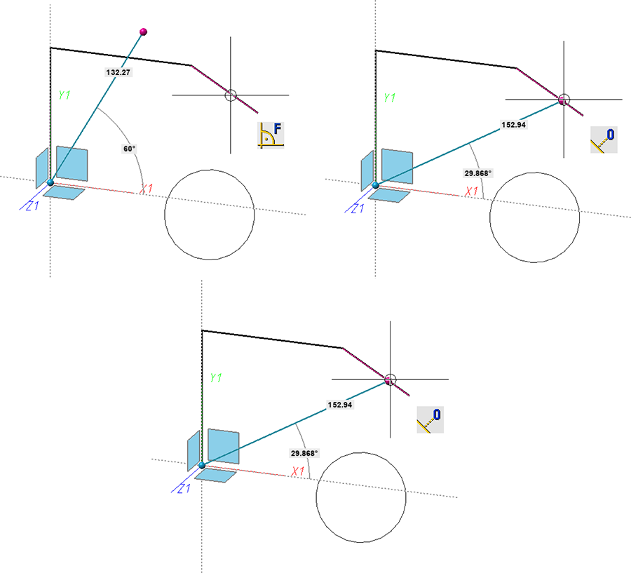
Furthermore, depending on the cursor position, both the point options
 (O) Online to edge through point as well as
 (F) Perpendicular base point
is displayed when the cursor is close to a straight line. For circles, the option (F) Perpendicular base point is also displayed. For arcs and ellipses the behaviour is the same.
If the cursor is placed near a circle, the options (F) Perpendicular base point and (T) Tangential point are now also displayed. For 3-D sketches, however, this only applies if the circle and the last point are in one plane. For arcs and ellipses the behaviour is the same.
![]() Please note:
Please note:
- Please note that the options X, Y and XY are only available in the Autopoilot if the points are located in the drawing plane.
- In contrast to planar sketches, the point option (T) Tangential point is only displayed on the autopilot for circles if the circle and the last point are located in one plane.
Taking into account of Plant Engineering parts
Connecting points of Plant Engineering parts are given special consideration in sketches. If the first point is a connecting point, this point is used to preset a grid direction. This means that the following lines are drawn in this direction.

Working with Sketches (3-D) • Sketch Functions (3-D) • Sketching Tool fpr Planar Sketches (3-D)