New Assembly
3-D Standard > New > Assembly 
Use this function to create a new 3-D assembly. Assemblies are used in 3-D to add further structure to the model drawing. Parts of the type Assembly are dummy parts with isolated points and a special ID. They consist of precisely one main part – the so-called main assembly part - and the sub-parts assigned to this part.
For further specification of an assembly, you can assign particular part types to it, e.g.:
- general assemblies,
- bolted assemblies,
- welded assemblies,
- mullion assemblies,
- glass assemblies,
etc.
Assemblies are marked in the drawing by means of large red isolated points. These points can be used to identify an assembly directly in the drawing.
When you call the function, HiCAD will open the Part attributes dialogue window. Specify the attributes for the assembly and confirm with Apply changes. HiCAD will then prompt you to specify the desired assembly points. You end the assembly specification by clicking the middle mouse button. You can then assign parts to the assembly: Activate the assembly and create new main parts, or drag parts into the assembly in the ICN.
Clicking on the symbol opens a pull-down menu with further functions:
|
|
Assembly Inserts an assembly as sub-part. |
|
|
Main assembly Creates a main assembly. A main assembly is a special assembly to which all other assemblies and parts are subordinated. Each model drawing can only have one main assembly. |
|
|
Use this function to replace a complete assembly with a dependent assembly - in the same way as with the Dependent part function. This is only possible for original assemblies that are
Dependent assemblies are marked in the ICN with the |


 symbol.
The Part CS of assemblies
Like any other part, assemblies, too, have a part coordinate system. This coordinate system can either be automatically determined by HiCAD, or determined by you during creation of a dummy assembly or during forming of an assembly from existing parts. For this purpose, a new parameter is available in the ISD Configuration Editor at Modelling > Part creation > Assembly.
The following settings are possible:
- Standard CS (default)
The Part CS will be determined automatically by HiCAD and corresponds to the World CS. There will be no further queries. This behaviour is identical to that of previous versions.
- Query
If this setting is active, HiCAD will ask you to choose a plane, as you would do for a processing plane. This plane is the top view plane of the Part CS. You have the following options to determine this plane: - You determine the plane by identifying, in any order, points, edges, surfaces and also processing planes in the model drawing. The Standard CS will then be rotated in such a way that the XY-plane lies in the selected plane.
- Press the middle mouse button to choose the World CS.
- Right-click to activate a context menu with further functions.
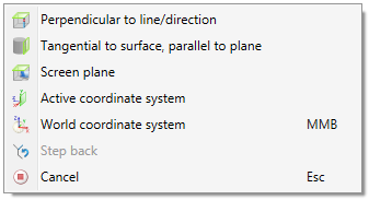
The functions of the menu work in the same way as the same-named functions for processing planes.
The settings in the Configuration Editor do not apply to main assemblies. For created new main assemblies the Part CS always corresponds to the World CS.
![]() Please note:
Please note:
- Extensive information on assemblies, main parts and sub-parts can be found in the topic Drawing Objects of the HiCAD Basics Online Help chapter.
- Before creating any 3-D parts we recommend that you read the information given in the topic Hints on Part Creation.
- A drawing can contain only one main assembly.
- Use the functions of the Assembly points menu to change or add assembly points. You can access the Assembly points menu by right-clicking either the assembly in the ICN or an assembly point in the drawing.
- If you want to combine already existing parts into an assembly use the Form assembly
 function in the context menu for parts.


Part Creation Functions (3-D) • Part Creation: Useful Hints (3-D) • Assembly Points and Assembly Article Number