Set Parameters for New Dimensions
3-D Dimensioning + Text > Tools > Dimension
When you specify the dimensioning settings with the functions

|
Set parameters for new general dimensions |

|
Set parameters for new parametric dimensions |

|
Set parameters for new constraint dimensions |
, the Dimension parameters window is displayed. It consists of the following tabs:
- Dimension lines
- Dimension line termination
- Dimension figure
- Dimension texts
- Tolerance
- Symbol
- Grid
- Further settings
- System
These tabs enable you to define all dimensioning parameters individually.
- Choose the desired settings or enter the desired values.
- Click OK to exit the window.
The settings will be regarded as the default settings for all subsequently created dimensions.

Dimension lines
In this tab you define parameters for the dimension lines and the projection lines. These are
- the visibility of the dimension lines,
- the colour,
- the parameters for internal/external dimensioning,
- the distances for parallel dimensions,
- the symbol for and the size of the dimension line termination. These values can be set separately for general dimensions, radius dimensions, heights above datum and running dimensions.
- the representation, excess length and visibility of projection lines. The parameters can be set separately for the first and the second projection line. This also applies to projection line visualisation. Furthermore, these settings can be defined separately for angular dimensions.
- Excess lengths on/off for linear, running, angular, arc and radius dimensions and heights above datum.
 Please note:
- The Int./Ext. dimensioning field is not active here. Use the Change parameters function to switch from internal to external dimensioning subsequently.
- The hiding of dimension lines (via the Visible checkbox) enables a representation of dimensionings according to DIN 86062, i.e. dimensionings with dimension figures, without dimension lines, projection lines and arrows.
Dimension line terminations
In this tab you can preset the symbol, length, width and colour of dimension line terminations. The settings can be applied separately for
- Distance dimensions,
- Angular and arc dimensions,
- Radius dimensions,
- Heights above datum, and
- Running dimensions.
Dimension figure
On this tab you define the representation and properties of the dimension figure.
Font
Here you select the font, colour, height and character set (the latter is only available if no HiCAD font has been selected). The character set determines which fonts will be offered for selection, e.g. if you choose "Chinese", only fonts that support Chinese characters can be selected from the list box.
For HiCAD fonts you can additionally specify the Aspect ration/Inclination of the dimension figure. If the aspect ratio is smaller than 1 the text will appear compressed. Conversely, the text will appear stretched if the aspect ratio is greater than 1. With an inclination of 0.00 degrees the text will be shown normal, with an inclination of 15.00 Grad it will be shown in italic type.
Representation of dimension figure
- In the Superscript decimal places starting from field you specify the superscription of decimal places. Such representations are, for example, required in construction drawings where dimension figures frequently appear in the format Metre.CentimetreMillimetre .
The font parameters of the superscript numbers correspond to those of the dimension figure, apart from one value for superscription and font size. Superscription and font size depend on the font size of the dimension figure. The calculation factors (superscription 50%, font size factor 66%) are pre-programmed, fixed values and cannot be changed.
- For (inch, am.) and " (inch, brit.) the decimal places of the dimension figure can also be displayed as fractures. The following options for fractures are available:
- No
- Automatic denominator
- Fixed denominator, reduce fraction
- Round value, fixed denominator, reduce fraction (only for parameter changes)
(1) Original value without fraction.; (2) Automatic denominator; (3) Fraction, round value, fixed denominator, reduce fraction, highest denominator 4
Representation
Here you specify the unit of measurement, the number of decimal places and the representation of non-relevant places. Possible units of measurement are in (inch, am.) and " (inch, brit.). Please note that in or " values are always converted into ft and inches, and the dimension figure will be output in mixed format, e.g. 1ft- 1.62 in bzw. 1'-1.62". 
The settings in the Representation area can be specified for general dimensions, angular dimensions and heights above datums.
2nd dimension figure
In addition to the actual dimension figure you can display a 2nd dimension figure, converting the existing dimension to another unit of measurement. For 2nd dimension figures you can specify the unit of measurement, the number of decimal places and the conversion factor can be specified. However, the latter can only be specified if the option None was chosen as unit for the 2nd dimension figure. In the other cases the factor results from the chosen unit of measurement. The 2nd dimension figure can be displayed above or below the 1st dimension figure. To do this, choose the desired setting in the Position field.
The parameters can be specified separately for general dimensions, angular dimensions and heights above datum. To display the 2nd dimension figure you need to activate the corresponding checkbox.
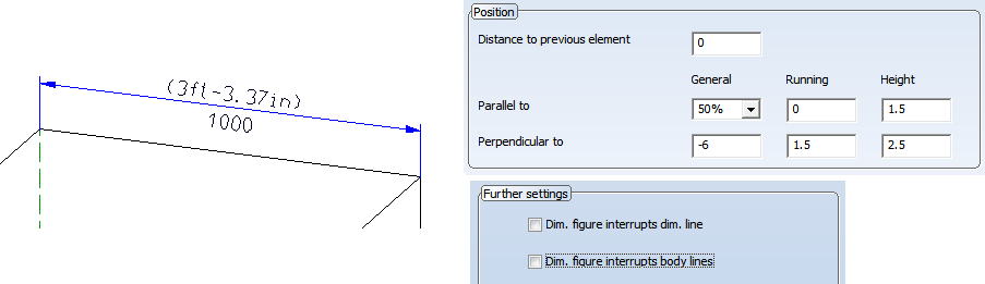
Position
In the Position area you determine the position of the dimension figure with regard to the dimension line. Also, you specify the distance to the previous element here, e.g. to a preceded auxiliary dimension text.
Please note:
- The settings for figure superscription cannot be applied to angular dimensions.
- If you want to display a 2nd dimension figure for existing dimensions, select the Change parameters function and activate the corresponding checkbox on the Dimension figure tab.
- If you want two dimension figures to be displayed, with one figure being placed above, and the other figure below the dimension line, you need to specify the position of the dimension figure perpendicular to the dimension line accordingly in the Position area, and on the Further settings tab, deactivate the interruption of the dimension line and the body edges by the dimension figure.
Dimension texts
Auxiliary texts can be assigned to the dimension figure, being either placed in front of it or appended to it. In the Dimension text tab, you define whether you want these auxiliary texts to be displayed and you specify the properties of the auxiliary texts. These are:
- the colour, font, encoding (character set) and text height
- the text alignment
- the distance to the previous element and the next line.
Tolerance
Here, you define the tolerance parameters. These are:
|
|
Symbol
Dimensioning symbols, e.g. the diameter sign, can be assigned to each dimensioning. In this tab, you define the size of the symbols and their position in relation to dimension figure and dimension line.
Use the Edit dimension figure function to assign a symbol to a dimension figure.
Grid
When placing dimension figures and dimension lines and rotating circle, radius and diameter dimensions the grid specified in this tab will be used.
If you want to use other grid line spacings or switch the grid off, change the settings accordingly.
Further Settings
Use this tab to specify further dimension parameters, such as:
- zero point specification for running dimensions, coordinate dimensions and heights above datum,
- symbols for arc, diameter and radius dimensions,
- behaviour of arc dimensions and angular dimensions when moving or rotating them.
When dimensioning the two edges displayed pink, the following two angular dimensionings are possible, provided that a switching of quadrants is allowed. If a switching of quadrants is not allowed, the second angular dimension (215°) is not shown. - the behaviour of dimension figures in case of collisions, i.e. the automatic prevention of dimension figure collisions, the use of leader lines etc.
- the creation of dimension figures with exclusions of dimension lines or body edges.
When you dimension an object, it can occur that dimension figures collide with part edges or dimension lines of a different dimension. If you activate the corresponding checkboxes, HiCAD will automatically create exclusions in the corresponding dimension line or part edge in order to improve the legibility of the dimension figure. The size of the exclusion is normally automatically determined by HiCAD. If the exclusion is too small, you have the option to additionally set an allowance for the height and width of the exclusion rectangle. The allowance is absolute and scale-independent. It can also be applied if the dimension lies on a hatching.
If the option Dimension figure interrupts body lines is active, you can determine on the System tab, in the Printed representation area, that dimension figures will be shown with white rectangular backgrounds in printouts.
With and without allowance for exclusion
- the allowing of angular dimensions greater than 180°.
- for radius dimensions: maximum dimension line length for a lengthening to the centre point.
Shortening of the dimension line by setting its maximum length
 for large radiuses in order to shorten the dimension line from the centre point; can be lengthened by moving of the dimension line.
System
Use this tab to specify settings which will globally apply to the current workstation and will be used for all subsequently created dimensions.
Dimension figure representation
Use these options to specify which separator for decimal places (point or comma) you want to use and according to which rules you want to round the dimension figure up or down. If you select "mathematical", the dimension figure will be rounded according to the common mathematical rules. If required, the dimension figure can also be generally either rounded up or down. Default setting is:  Point, Mathematical.
Printed representation
If the option Dimension figure interrupts body lines is active, you can determine on the System tab, in the Printed representation area, that dimension figures will be shown with white rectangular backgrounds in printouts.
This setting will be applied immediately. A restarting of HiCAD will not be required.
Behaviour during creation
Here you specify what you want HiCAD to do if a processing plane is active, or if a selected dimension point is not clearly identifiable (e.g. because of overlapping points).
- Project linear and arc dimensions onto processing plane?
If you choose No, the processing plane will be ignored, if you choose Yes, the dimension will be projected onto the active processing plane. This applies to linear dimensions, arc dimension structures, and individual arc dimensions created with the Arc dimension, via 2 points... function. This enable the creation of a proper arc dimension if centre and points on the arc are not located in one plane. If you choose Query, HiCAD will check for the dimensioning functions whether a processing plane is currently active. If this is the case, you will be asked whether the dimension is to be projected onto this plane.
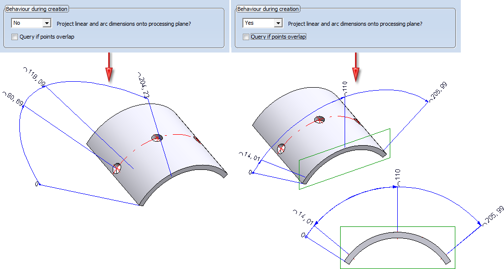
Example of an arc projection. Left: Without processing plane; Right: With projection onto processing plane
- Query when points are overlapping
If this checkbox is active and a dimension point is not clearly identifiable, e.g. because of coincident, overlapping spatial points, HiCAD will ask you which of these points you want to use. Select the required point by specifying the corresponding point number. HiCAD assigns consecutive numbers from the back to the front, i.e. the foremost point has the highest number. HiCAD suggests this point by default.
If the checkbox is not active, the foremost point is always selected.
If you apply the dimensioning in the front view (2) as shown in the example below (1), there are coinciding spatial points: Let us assume that we want to create an axially parallel linear dimension in front view (3). In case (a) we select the foremost, in case (b) the rearmost point. The difference is clearly visible in the axonometric view (4):
- Dimension assignment
You can assign the dimensions either to the active part or to the part to which the 1st dimension base point belongs. This parameter can be preset via the Configuration Editor, at System settings > Annotations > Dimensioning, 3-D > Interactive dimensions > Dimension assignment. The default setting is Active part.
Adjusting of dimension lines when changing the scale
Here you can specify the behaviour of the dimension lines in case of scale changes:
|
Option |
Effect |
|---|---|
|
Do not adjust |
The points of the dimension line are scaled in the same way as the corresponding part. |
|
Scale |
The points of the dimension line are adjusted scale-independently. |
|
Scale selectively |
This is the default setting. The points of the dimension line are only adjusted scale-independently if they are located outside the part. Otherwise, HiCAD proceeds in the same way as with the first option (Do not adjust). |
(1) Original, Scale 1:1, (2) Scale 1:5, Do not adjust, (3) Scale 1:5, Scale
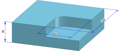
The following image illustrates the Scale selectively option. The dimensions belong to the left cuboid, with the base point highlighted in red lying outside this cuboid. If the Scale selectively option is active, the length of the projection line starting from this base point remains unchanged, while the other lines are adjusted accordingly in case of a scale change.
Settings for parametric dimensions
These options are available for parametric dimensions and HCM dimensions. They enable you to define the behaviour of the dimension line and dimension figure during zooming, via the checkboxes
- Size of dimension figure is zoom-independent (Default
 ) )
) ) - Position of dimension line is zoom-independent (Default
 )
)
(Left: Original; Right: (1) Only figure zoom-independent, (2) Both zoom-independent, (3) Both zoom-dependent)
The System tab is not shown if you want to apply subsequent changes to settings for individual dimensions or dimension elements.
