Standard Processings
3-D Standard > Standard Processings
You use the functions of the Standard Processings menu to insert standard bores and threads, free bores or shaft processing like relief grooves or feather keyways.
|
|
|
|
|
|
|
|


Clicking  opens a menu with further functions for Standard Processings.
 Please note:
- Alternatively, you can access the functions for Standard Processings via the context menu for parts or via the context menu for Standard Processings.
- For a subsequent modification of existing Standard Processings you can use the functions of the context menu (right-click Standard Processing). Standard processings can also be edited by double-clicking on the corresponding entry in the feature log. This applies to all standard processings for which a catalogue selection is possible as well as through holes and letterings.

Notes on threads
In the catalogues for thread standards, internal (KERDI) as well as external core diameters (KERD) are managed. You can specify in the Configuration Editor at System settings > Standard Parts > Core diameter which of these values are to be used as core diameters for threads. You can choose between Bore diameter, Internal thread and External thread. The default setting is Bore diameter, i.e. the bore diameter of the screw starter will be used as the core diameter for threads (in the catalogues: column BORD, e.g. for DIN 13). If you change this setting, please note that the re-calculation of Standard Processings, boltings etc. in drawings from older HiCAD versions might lead to collisions.
After a new HiCAD installation the new default setting will be Bore diameter. After an update installation from versions older than 2015 (2000.0) the previous default setting will be preserved, i.e. the bolt diameter will be used. If you do not want this, change the settings in the Configuration Editor accordingly.
Representation of threads in shaded views
Threads can be displayed with a thread texture or transparent. Which of these representation types is to be used by default can be set in the Configuration Editor at System settings > Visualisation > Views > Thread representation in shaded views. Here you have the following two options:
- With thread texture
This is the ISD default setting, which displays the pitch and the chirality of the thread in a realistic manner. However, this is only possible for shaded views, and not for the Glass model, HiddenLine or QuickHidden Line view.
- Transparent
If you select this option, threads will be displayed transparent in shaded views.
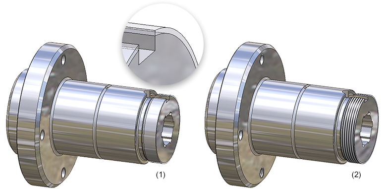
Flanged shaft with transparent (1) and textured (2) thread representation
Independently from these pre-settings in the Configuration Editor you can also determine the representation of shaded threads for each view of a model drawing separately. To do this, open the Views Ribbon tab and choose Representation > Shaded > ...).
|
|
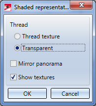
Shaded representation (Active view) With this function, the active view of thread representation can be changed. For that, the dialogue window Shaded representation is shown:
Choose the desired representation by activating the corresponding option and close the window by clicking OK. |
|
|
Shaded representation (All views) This function corresponds to the same-named function beneath Active view, with the difference that it affects all views of a model drawing. |


Only one thread will be equipped with texture in case of multiple insertion via grid.


Standard Parts and Standard Processings (3-D) • Multiple Fitting on a Grid (3-D)