3-D Standard > Process > Trim  > Divide along direction
This function allows you to divide parts of the type Solid into several sections along one direction. Different division options are available, for example, the individual parts can have different lengths. In addition, a corresponding feature is created with this function so that the division can also be edited later.
The dialogue window
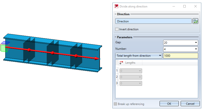
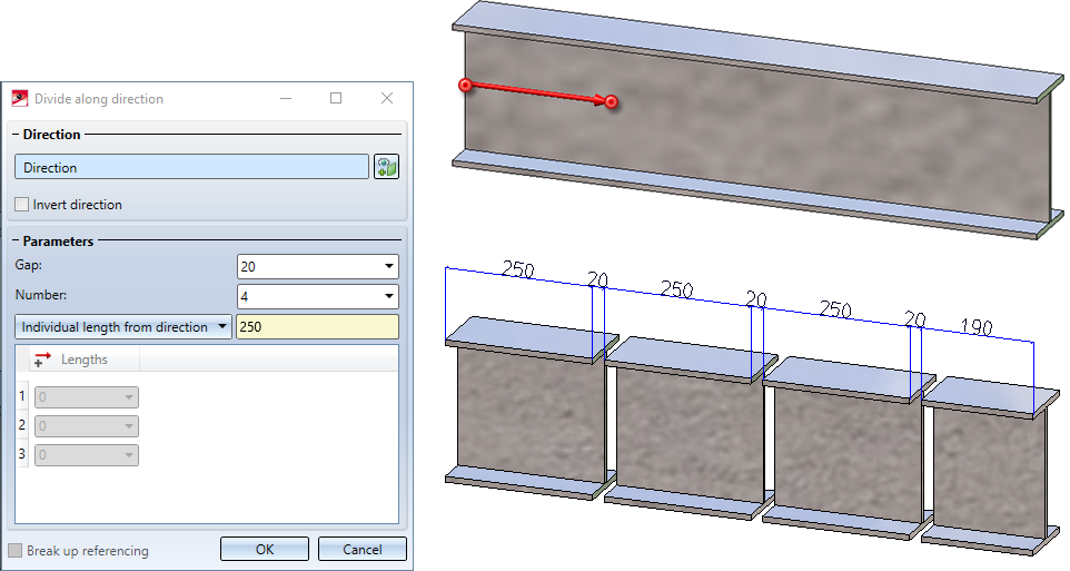
When you call the function the following dialogue window will be displayed:
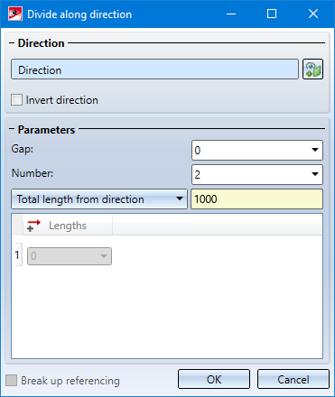
Direction
After calling the function, the Select direction field will be active (highlighted in colour). Then determine the direction in which the division is to be made. This can be done by selecting two points, an edge or a surface. If a surface is selected, then the surface normal is used as direction. The selected direction is visualized by a coloured arrow in the drawing.
If the active part is a steel engineering beam, the beam axis is automatically suggested and visualized as the direction when the function is called. 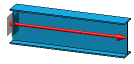
To change the direction, click on the Select direction  symbol.
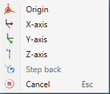
While selecting the direction, you can right-click to activate a context menu with additional functions.
If the displayed direction shall be reversed, activate the Invert direction checkbox.
Parameter
|
Gap |
Distance between two segments |
|
Number |
Number of segments |
|
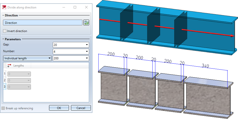
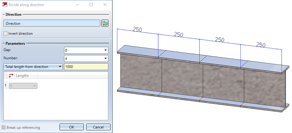
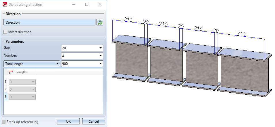
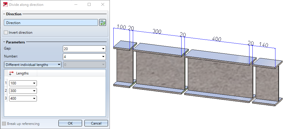
Length of segments |
To determine the length of the segments, the selection box offers various possibilities. Please note that the total length of the resulting segments + gap always corresponds to the total length of the initial part. This means that the length of the last segment is calculated automatically and may differ from the individual length specified.
|
|
Break up referencing |
If the initial part is referenced, the referencing can be broken up by deactivating the checkbox. When breaking up the referencing, a HELiOS document and article master existing at the initial part is also deleted. If the checkbox is active, the referencing is assigned to the first part in the direction of the division. This also applies to a HELiOS document/article master existing at the initial part. The other parts are not referenced. |
The direction, each division point and each gap are visualized in the drawing.
Incorrect or missing entries are marked with the  symbol. If you move the cursor over the symbol, a corresponding message is displayed. If the function cannot be executed with the entered data, this is indicated by the
  symbol on the OK button at the bottom of the dialogue.
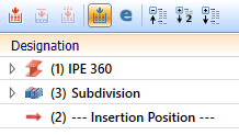
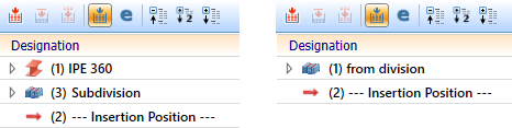
Each part is a separate part in the part structure - on the same hierarchy level as the initial part and with the same name. The initial part is assigned a feature with the name Subdivision, all other parts are assigned a feature with the name from division. The division can be edited by double-clicking on one of the features. All parts are adjusted accordingly.
![]() Please note:
Please note:
- The function is always applied to the active part. The part must have the geometry type Solid.
- The total length of the resulting parts (+ gap) always corresponds to the total length of the initial part.
- If the initial part (not referenced) has a HELiOS document and article master, then this master is also assigned to the parts.
- The function can also be found at Steel Engineering > Lengthen > Divide.
Please also read the notes in the Update division feature paragraph further down.

Examples
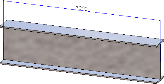
In the following example, the direction has been determined by two points.
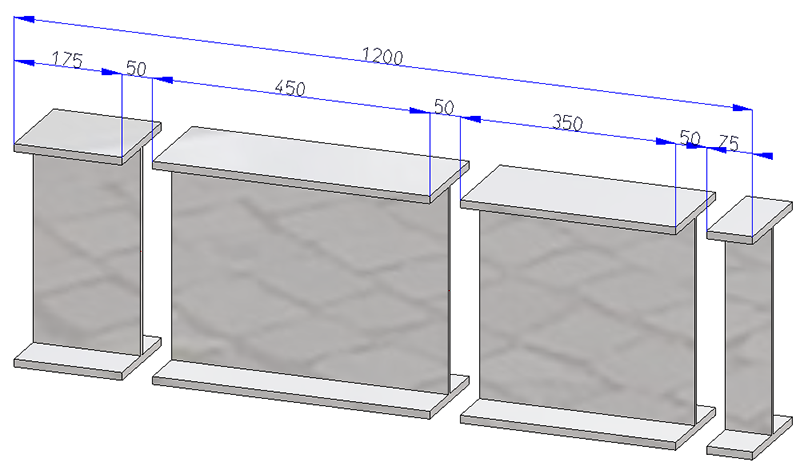
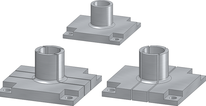
The following figure shows a divided 3-D part.
Update division feature
If you make changes to the initial part on features coming before the Subdivision feature, only the initial part will be recalculated. The division is performed at the same position relative to the part coordinate system. This means that neither the division points nor the parts are recalculated.
Example 1:
The following figure shows a divided IPE 240 beam.
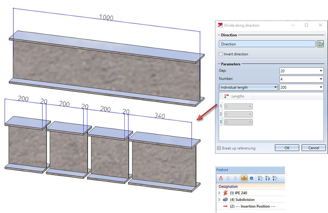
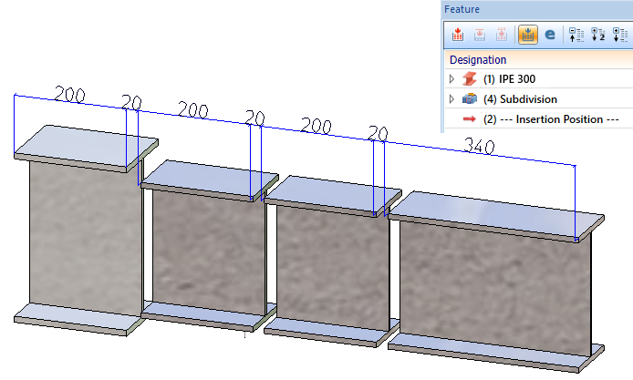
If you exchange the beam, e.g. with an IPE 300 beam, you get the following result:
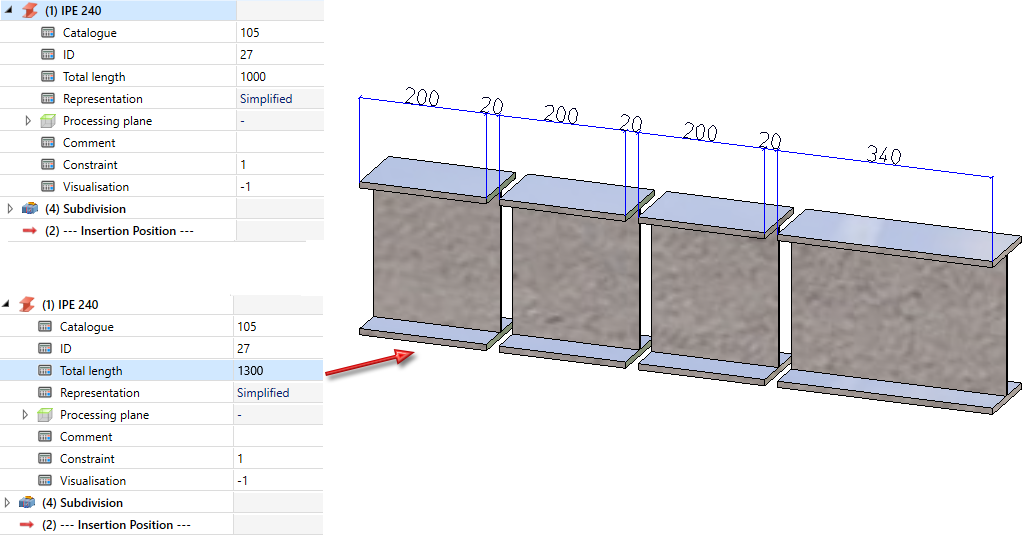
Example 2:
Again we take a look at the image from Example 1. If the total length of the beam is changed by the feature, no geometric change is visible.
If you want to adapt all sections to the changes, use the Update function in the feature context menu of the division.

A recalculation of all parts takes place automatically when you change the part feature.
