Internal/External Thread
3-D Standard > Standard Processings > Thread 
You use this function to create internal or external threads for cylinders.
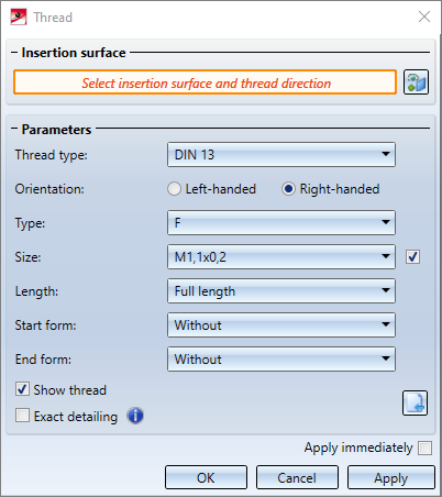
Choose the Internal / external threads function. The Thread dialogue window will be displayed.
Insertion surface
After calling the function the Select insertion surface and thread type field is active and highlighted by an orange frame. Identify a cylinder surface or an edge on one side of the cylinder. In the process, the thread direction will also be determined (depending on the side/edge on which you identified the surface) and visualized in the drawing.
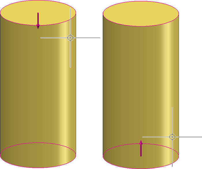
If the identified surface is a shaft surface, an external thread will be created; for a bore surface an internal thread will be created.
To change the surface selection, click on the  symbol and determine the desired surface.
Parameters
In the Parameters area you specify the parameters for the thread.
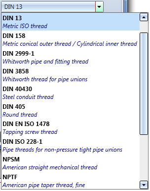
- Thread type
Choose the desired thread type from the listbox.
- Orientation
Here you determine, by activating the desired option, whether a left-handed or right-handed thread is to be inserted. - Type
Depending on the selected thread type, different sub-types are available, e.g. short or regular threads, fine or coarse threads etc. Select the desired sub-type from the listbox.
- Size
Choose the thread diameter and the pitch (distance between two thread lines) here. If you want the nominal diameter to be determined automatically, activate the checkbox. In this case the thread diameter matching the diameter thread area will be applied automatically. If, for example, you have selected the thread type DIN 13 for a shaft surface with the diameter 48, then an external thread M48 will be automatically applied.
- Length
Here you specify the length of the thread. - Full length
Here the thread runs along the entire selected thread surface, i.e. completely through. - Fixed length
Here you specify a particular thread length. The starting point for determining the length is the cylindrical surface, which is closer to the cursor when the lateral surface is selected. - To point
Here the thread depth is determined by determining a point. The starting point for removing the length is the cylindrical surface, which is closer to the cursor when the lateral surface is selected.
- Start form/End form
Here you can define the form of the thread start and the thread end. The following options are available:
|
External thread |
Internal thread |
|---|---|
|
Without |
Without |
|
Chamfer |
Countersink The countersink will only be created if the Exact detailing checkbox has been activated. |
|
Cone point |
|
|
Tapering |
|
|
Runout Select the type of length determination. The available options depend on the setting selected for the thread length.
|
Runout |
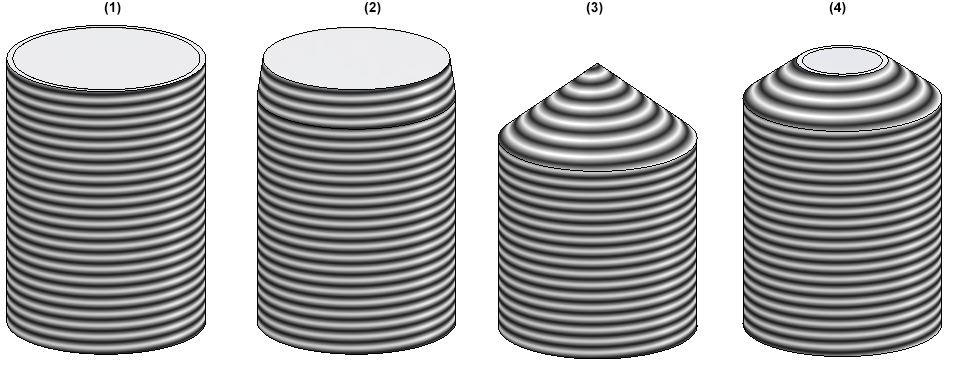
(1) Without, (2) Chamfer, (3) Cone point, (4) Tapering
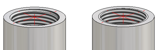
Internal thread with and without countersink
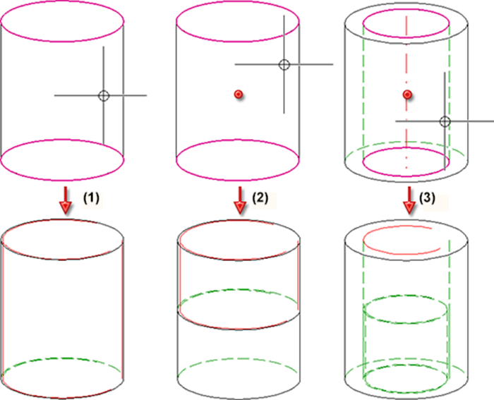
(1) Thread DIN 13 -M50x1.5, (2) Runout length 20, (3) Runout factor 8, (4) Internal thread DIN 40x1.5 with runout
Show thread/Exact detailing
Use these checkboxes to determine whether the thread is to be shown and if so, with exact detailing or not. Please note that for external threads the start/end form Chamfer is only created when the Exact detailing checkbox is activated. The same applies to internal threads for the start/end form Countersink.
Click on the  symbol (only available when the checkbox is active) to apply the settings specified with the Settings for shaft processings function.
Apply immediately
If this checkbox is active, the thread will be inserted immediately after the parameters have been determined. If the checkbox is inactive, a preview of the thread is displayed and the parameters can still be changed. Only after a click on the Apply button (or on OK or by pressing the middle mouse button) will the thread be inserted.
The dialogue window remains open after insertion of the part, so that further threads can be inserted without having to call the function again. Click OK to close the dialogue window.
Incorrect or missing inputs will be marked with the  symbol. If you move the cursor over the symbol, a corresponding error message will be displayed. If the function cannot be executed with the entered data, this will be indicated by the
  symbol on the OK button.
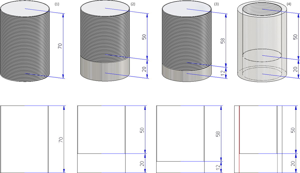
(1) External thread, full length; (2) External thread, to point; (3) Internal thread, to point
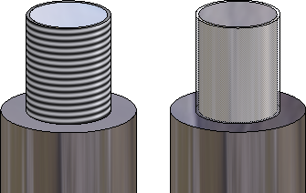
Outer thread. Left: With texture, Right: Transparent
 Please also read the notes on the representation of threads in shaded views.
In the catalogues for thread standards, both the inner core diameter (KERDI) and the outer core diameter (KERD) are managed. Which of these values is used as core diameter for threads is defined in the Configuration Editor at System settings > Standard Parts > Core diameter. There you can choose between bore diameter, internal thread or external thread. The default setting is drill diameter, i.e. the core diameter for threads is the diameter of the pilot drill (in the catalogues: column BORD e.g. for DIN 13). If you change this setting, please note that collisions may occur when recalculating standard processings, boltings, etc. in model drawings created with older HiCAD versions.


Standard Processings (3-D) • Settings for Shaft Processings (3-D) • Shaft Generator (3-D) • Shaft Elements (3-D)