Create New Cut-Out
Views > Edit > Create new cut-out 
 This function will always be applied to the active view. Please select the desired view before you call the function.
To create a new cut-out, proceed as follows:
- Specify the Sketch for cut-out path. Please note that this sketch must be closed.
- If you want to apply an existing sketch, click
 , and identify the sketch in the drawing.
 - If you want a
new sketch to be created, click
 , and use the sketch functions to draw the sketch.
- If you want the sketch to be deleted after you have created the cut-out, activate the Delete after creation checkbox.
- Define the depth
of the cut-out by specifying a point for the cut-out floor. To do this, click
 , and specify the point you want.
 - Use the Preview button to check the cut-out.
- You can change the direction of the cut-out by activating/deactivating the Reverse direction checkbox.
- If you want the section surfaces to be hatched, activate the With hatching checkbox and then choose the hatching data. The hatch pattern is selected in the same way as for sectional views.
- Click Createif you want the cut-out to be generated with
the current settings.
(1) active view, (2) sketch, (3) cut-out floor, (4) cut-out
![]() If the sketch lies in the screen plane, the cut-out is directed from
the specified point to the viewer; if not, it is directed from the point
to the sketch plane. If the point lies in the sketch plane, the cut-out
is created in Z-direction of the sketch.
If the sketch lies in the screen plane, the cut-out is directed from
the specified point to the viewer; if not, it is directed from the point
to the sketch plane. If the point lies in the sketch plane, the cut-out
is created in Z-direction of the sketch.
Please also read the notes on the purposes and representation of sketches. Sketches with the purpose Part will be cut in cut-outs, sketches with the purpose Create/Edit will not be cut.
Cut-out views are marked with the  symbol in the ICN.
Important notes on cut-outs
- The active view must not be an opened sectional view or a surface sectional view. Only standard views or "standard" sectional views are permitted.
- The active view can have several cut-outs.
- The settings of the Hatch section view + cut-out function (RMB > Properties ...) may be used when displaying the section surfaces.
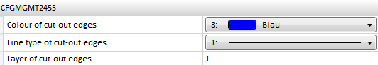
- You can specify the representation of edges in cut-outs in the Configuration Editor, at Drawing > Views >Representation of special lines. There you can select a colour, a line type and a layer for the edges:
- Whether a part is to be considered in a cut-out depends on its section behaviour, which can be specified with the Cut in sectional view + cut-out function.
- After transformation of a 3-D model, the cut-outs can be adjusted automatically. To do this, select Drawing > Extras > Tools, then choose one of the following options:
- Recalculate cut-outs, sectional and detail views (only active view)
- Recalculate cut-outs, sectional and detail views (all views)
- If a sketch that has been parameterised with HCM constraints contains variables, these will automatically be defined as variables of the view. When using the sketch in a detail view, a sectional view or a cut-out. If you then change the value of the view variables, all views of the current drawing will be updated and the corresponding detail views, sectional views and cuts-outs will be adjusted accordingly. The original sketch, however, remains unchanged. This means that you can adjust view fast and easily without having to change the corresponding sketch.
- Cut-outs that are not up to date are indicated in the ICN by strikethrough view names and by a red cross in the drawing. For example, this is the case if you are working with sectional or detail views and transform the model after definition of the cut-out, or if you apply Boolean operations to the model.
If you do not want the crossed-out representation in the drawing, you can change this in the Configuration Editor at System settings > Visualisation > Views, where you can deactivate the Cross out old cut outs, sectional views and detail views in graphic checkbox.
- To update cut outs, choose Views > Edit > Update
 .
.


View Functions (3-D) • Special Views (3-D) • Hatching in Sectional View and Cut-Out (3-D)