Exploded view > Motion type > Dir. 
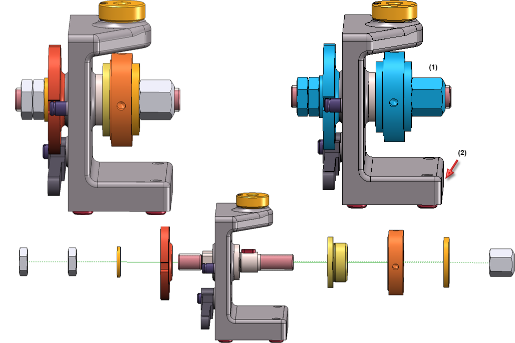
This function allows you to define displacements with automatic direction in the Exploded view mode. As with the Move transformation, several parts are linearly displaced simultaneously. In contrast, these parts are not moved with the same distance, but are distributed along the selected direction relative to a certain part (the so-called fixed part). This makes it possible to move several parts in one step simultaneously in positive and negative direction - depending on the position of the parts in relation to the selected fixed part.
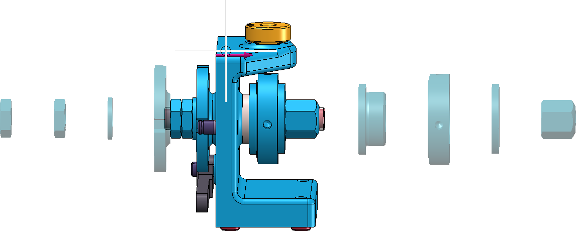
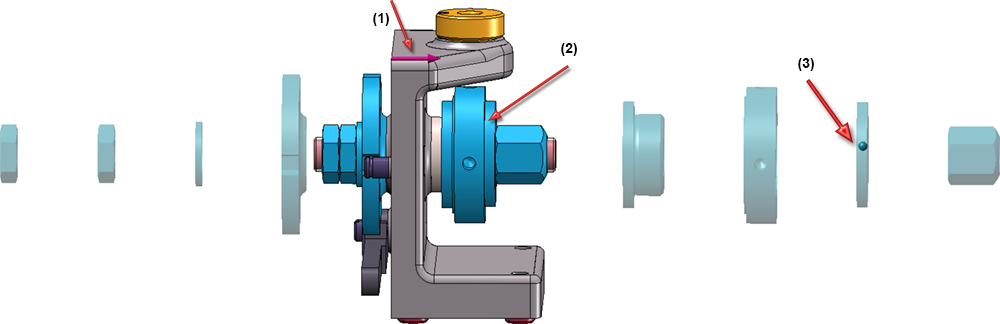
Let's take a look at the original drawing shown in the following image on the left. We want to achieve that the selected parts (1) - highlighted in blue in the illustration - are moved on both sides in one step in relation to the fixed part (2), depending on their position in relation to part (2). The desired result is shown in the image below:
To achieve this, use the AutoDirection function. When you call the function, the same-named dialogue window will be displayed:
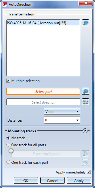
 When using the AutoDirection function, you normally want to select multiple parts; therefore, activate the Multiple selection checkbox.
- In the next step you determine the settings for the AutoDirection function.
Select fixed part
First you determine the fixed part, i.e. the part from which the parts contained in the selection list are to be moved in the selected direction - positive and negative.

To do this, click on the  symbol and select the desired part. The mane will be automatically entered in the input field.
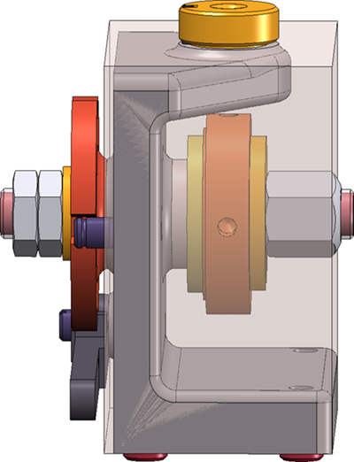
Please note that the displacement of the selected parts always refers to the so-called bounding box of the fixed part, i.e. to the smallest cuboid that completely encloses the part. If we look at our example, the bounding box of the fixed part looks like this:
Distance determination and direction
Three different methods are available for determining the distance. Please note that the start point of the displacement is always the bounding box of the fixed part.
- Value input
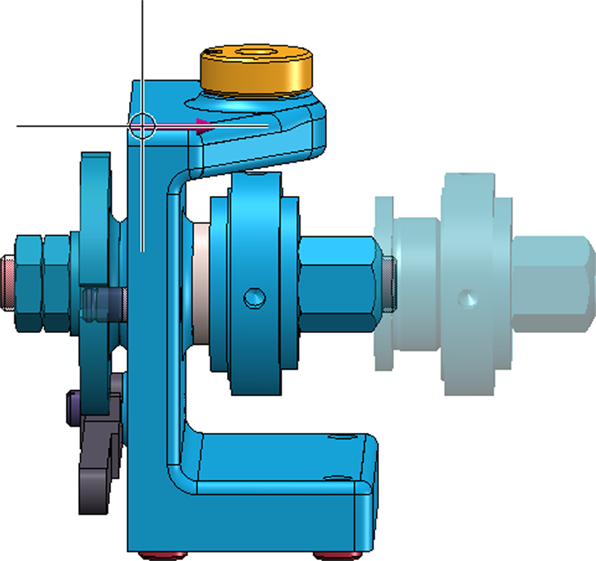
The selected parts are moved by a fixed value. The starting point for the displacement is the bounding box of the fixed part. If, in our example, the direction indicated in the image has been selected and 0 has been entered as the value, this is the zero position, i.e. the start point of the displacement. The first part (on the right) then virtually lies on the outer surface of the bounding box.
If you change the value to e.g. 30 and choose the same direction, the result looks like this:
The first part to be moved to the right and also to the left has the selected distance from the bounding box of the fixed part, all other parts are moved at the same distance from each other. The bounding box of the parts to be moved is the decisive element, too.
- Dynamic
No fixed distance value is specified here, but the distance of the displacement is determined dynamically with the cursor.
- Reference part
Here the displacement refers to a specific part of the selection list. After determining the direction, HiCAD prompts you to select the desired reference part. This part must be part of the selection list, otherwise a message will be displayed. HiCAD then automatically visualizes a point on the selected reference part. This point serves as a slider. Drag this point to the right to move the reference part. When the point is moved, the distance between the fixed part (bounding box) and the reference part is selected as the total distance. The parts in front of the reference part are then distributed evenly over this total distance. This results in the individual distance between moved parts. If we look again at our example with direction (1), reference part (2) and point (3), then the parts lying in front of the selected reference part are distributed evenly between the fixed part and the reference part.
After you have selected the type of distance determination, define the direction of the displacement. If the Select direction field is highlighted by an orange frame you can determine the direction directly. If this is not the case, click on the  symbol. The direction can be determined by selecting two points, by selecting an edge or by selecting a surface. In the case of a surface, the direction is determined by its surface normal.
Alternatively, to determine the direction, you can also use the functions of the context menu, which you activate with a right-click.
- In the lower area of the dialogue window, you can determine whether mounting tracks are to be entered in the model drawing that mark the course of a transformation.
If the Apply immediately checkbox is active, the transformation will be immediately accepted - as shown in the preview - and entered into the explosion log, i.e. you do not have to click the Apply button. If further parts are selected immediately afterwards - without changing the other settings - the same transformation is carried out immediately for these parts without the parts appearing in the selection list.
If the checkbox is not active, then use buttons. If you click OK the transformation will be accepted and the dialogue window is closed. If you click Apply the current transformation will be accepted. Unlike OK, the dialogue window will not be closed here, so that further transformations can be defined. If you click Cancel the dialogue window will be closed. Transformations that have not yet been adopted are lost.
Each applied transformation will be logged in the Exploded view docking window. Exploded views can be subsequently edited via this log.
![]() Please note:
Please note:
If the parts to be transformed are assigned to axes, crosshairs etc., then these have an influence on the size of the bounding box. This can lead to the case that the parts are not moved in the original order. To avoid this, you must delete the axes or crosshairs of the parts.


Exploded View • Create Exploded View • Representation Functions