
Project: HiCAD Sheet Metal
The settings from the system files ABWPAR.DAT and ABWCOL.DAT have been moved to the Configuration Editor.
You can now find the settings from those DAT files in the following directories:
|
Sheet Metal > Sheet development Sheet Metal > Default setting Compatibility > Sheet development up to HiCAD 2016 |
|
|
Compatibility > Sheet development up to HiCAD 2016 > Extended settings |
The two Design Variants Sheet corner with stiffener (riveted) and Sheet corner with puzzle piece have been revised and combined into one function. This also allows the insertion of sheet corners without stiffener.
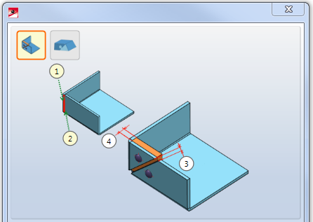
The insertion of these Sheet Metal Design Variants takes place via the Civil Engineering functions docking window at Sheet Metal > Sheet corner with stiffener or puzzle piece  . In the displayed dialogue, you can then choose between clicking on the Stiffener or Puzzle piece icon.
|
Sheet corner with stiffener |
Use this Design Variant to create a sheet corner with or without stiffener between 2 sheet flanges. The flanges can have different lengths and different bend angles. For insertion, identify the two front sides of the flanges. Activate the Use stiffener checkbox if you want to create a riveted connection. From a multitude of available fasteners (e.g. SFS or Titgemeyer) select the one you need. |
|
Sheet corner with puzzle piece |
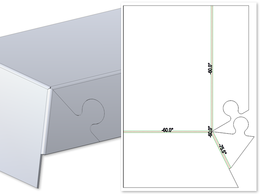
Use this Design Variant to create a sheet corner with a puzzle piece between 2 sheet flanges. The flanges can have different lengths and different bend angles. For insertion, identify the two front sides. The connection will be applied to the last identified flange. If you want a laser cut-out, activate the corresponding checkbox and enter the laser beam diameter for the cut out. If required, change the parameters of the puzzle piece. |
After entering all required data you can create the connection. Click Preview to check and, if required, modify the connection. If you click Apply, the sheet corner will be created, and the dialogue window remains open, allowing you to change the data or to switch to the other sub-variant, i.e. Puzzle piece ![]() or Stiffener
or Stiffener ![]() . the data to other sheet corners. If you click OK,the connection will be created, and the window will be closed. Clicking Cancel closes the dialogue window and discards the data without creating the connection. .
. the data to other sheet corners. If you click OK,the connection will be created, and the window will be closed. Clicking Cancel closes the dialogue window and discards the data without creating the connection. .
Incorrect inputs are marked with this symbol  . When you move the cursor over the symbol an error message will be displayed.
If the function cannot be executed with the entered data, this symbol  will appear at the OK button. When you move the cursor over the symbol an error message will be displayed.

Sheet corner with stiffener
Sheet corner with puzzle piece
Composite sheets, such as ALUCOBOND panels, are folded along milling edges. The resulting milling edge zones differ geometrically from the cylindrical bend zones. Therefore, the Fold flange  function now offers the additional option to choose milling edge zones and milling tools.
The following options are available:
|
|
Bend zone The bend zone has the specified bend radius. |
|
|
|
Milling edge zone Bend zone with the selected tool (milled inside). |
|
|
|
Milling edge zone inverted Bend zone with the selected tool (milled outside). |
|
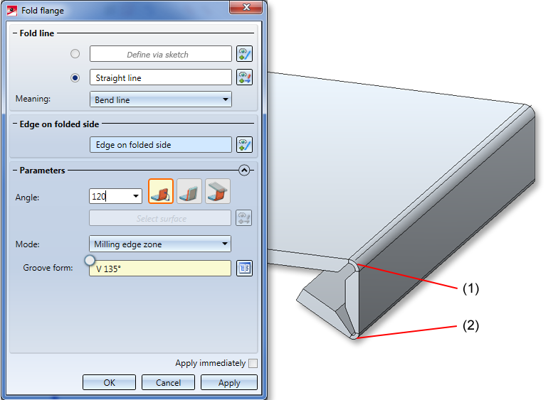
(1) Fold line defined by sketch, milling edge zone with groove form 90°
(2) Fold line on straight line (mid point of flange), milling edge zone with groove form 135°
Some CAM systems (e.g. CobusNCAD) do not support arcs at bend zone ends. To create bend zones suitable for milling, you can now use the Trim corner function to trim transitions with two or three milling edge zones in your sheet metal drawing. First activate the icon for the number of milling edge zones to be trimmed and then identify the milling edge zones. This creates 2 straight lines as an extension of the flange edges converging in the milling edge zone.
The ALUCOBOND SZ 20 cassettes were edited with the new Trim corner function having bend zone ends suitable for milling.
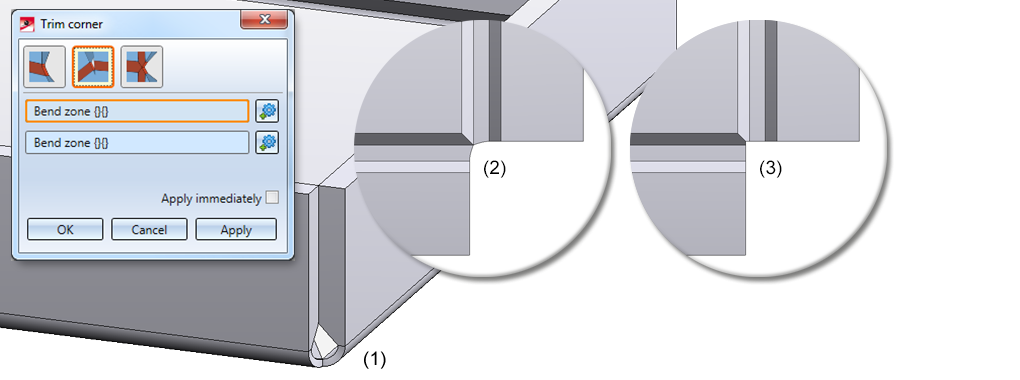
Trim corner, 2 milling edges
(1) Original situation
(2) View of original situation in the bending simulation (top view)
(3) Trimmed milling edge zone (top view)
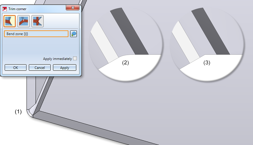
Trim corner, 1 milling edge zone
(1) Original situation
(2) View of original situation in the bending simulation (top view)
(3) Trimmed milling edge zone (top view)
With composite panels (e.g. ALUCOBOND) it is often necessary to process the edges in such a way that a milling edge occurs. For this reason, it is now possible to finish these flanges in Corner processing/Mitre within one sheet or between different sheets  .
.
With the modes Mitre cut and Mitre cut, with neighbours you are allowed to select the option Sheet edge as milling edge ![]() for fitting parameters. For the Groove form you can choose the matching milling tool from the Composite panels, groove form catalogue.
for fitting parameters. For the Groove form you can choose the matching milling tool from the Composite panels, groove form catalogue.
(1) Composite panels before processing
(2) After processing, mode Mitre cut, flanges with milling edges
(3) After processing, mode Mitre cut, with neighbours, flanges with milling edges, milling edge zone linear
When using the function New sheet along sketch  for the creation of a sheet from only one circular arc, one short, tangentially connected straight line element needed to be added at one end of that circular arc.
To simplify things, this element will now be added by HiCAD automatically as a flange (double tolerance, i.e. 0.002 mm) at the start of the circular arc.
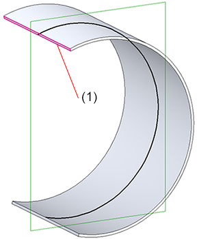
(1) Tangentially connected flange, 0,002 mm
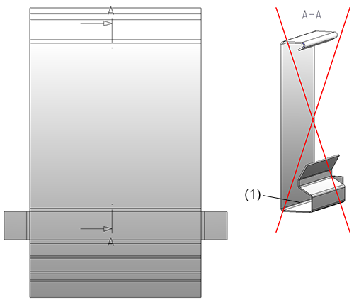
In previous versions the direction symbol for the processing direction was not visible in the DXF export if it was located on the rear side of the sheet development. On facade trays (e.g. ALUCOBOND trays) the direction symbol is often located on the front side of the trays. The development will then be carried out from the rear side in order to display the milling edges. Here, too, the direction symbol would not be visible in the export.
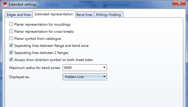
To visualize the direction symbol on the other sheet side, choose Sheet development > Update> Default setting and then, in the opened dialogue window, click on the Extended settings icon. In the next dialogue window, open the Extended representation tab and activate the Always show direction symbol on both sheet sides checkbox to copy the symbol to the other side of the sheet.
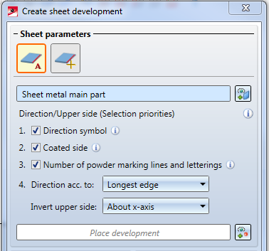
If you choose Sheet alignment: Automatic  in the Create sheet development dialogue window and select the Favourite COBUS NCAD, the option Invert upper side: About x-axis will now be set.
Changes to Favourites only affect initial installations; Favourites remain unchanged. Existing Favourites in an update installation remain unchanged.
HiCAD now also supports the placing of Eternit panels .
The semi-finished product data for Eternit panels can be found in the Catalogue Editor, at Factory standards > Sheets > Eternit, where you will find the following tables:
The semi-finished product dependent part colours are defined in the tables of Factory standards >Surface treatment > Profile and Element Installation > Eternit.
In the Catalogue Editor at Sheet tools > Moulding tools you can find a new table called Undercut bore for Eternit Tergo und Tergo+ undercut bores.
Insertion in HiCAD takes place in the same way as the other moulding tools (e.g. beadings or vents), i.e. via the function Sheet Metal > Further Tools > Moulding tools  .
.
(1) Undercut bore
(2) Undercut bore with bolting
The settings for Sheets with identical cross-sections are now available as a sub-entry of Sheet Metal.
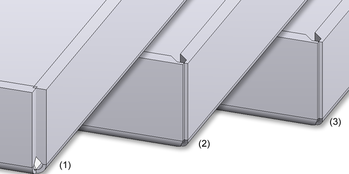
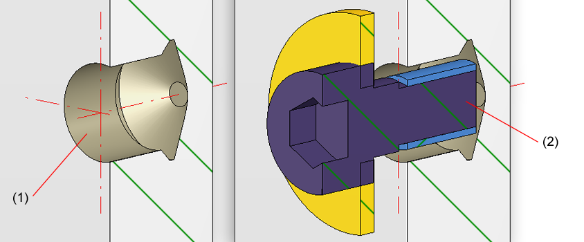
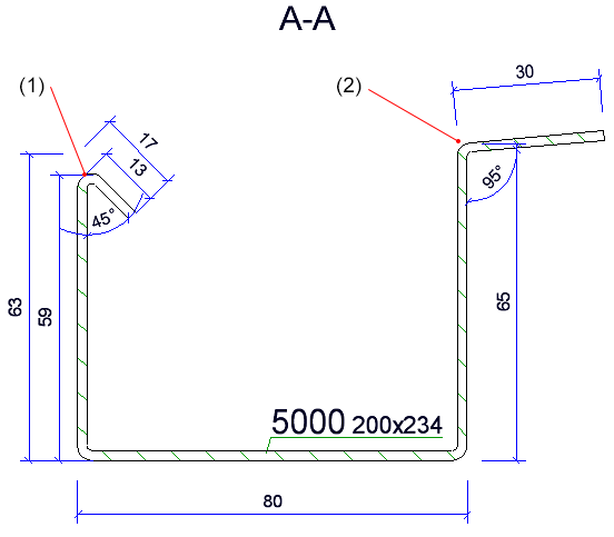
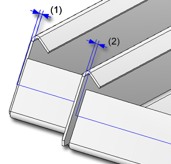
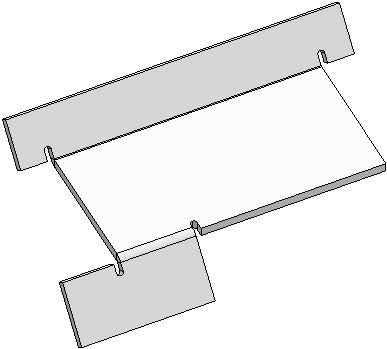
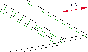
For flange lengths of sheets in sectional views, the following base point will be dimensioned:
The image below shows an example. The flange (1) has been attached with an angle of 135°, the flange (2) with an angle of 85°. In the sectional view, the tangential point is dimensioned for flange (1), and the theoretical intersection point for flange (2) is dimensioned as base point.
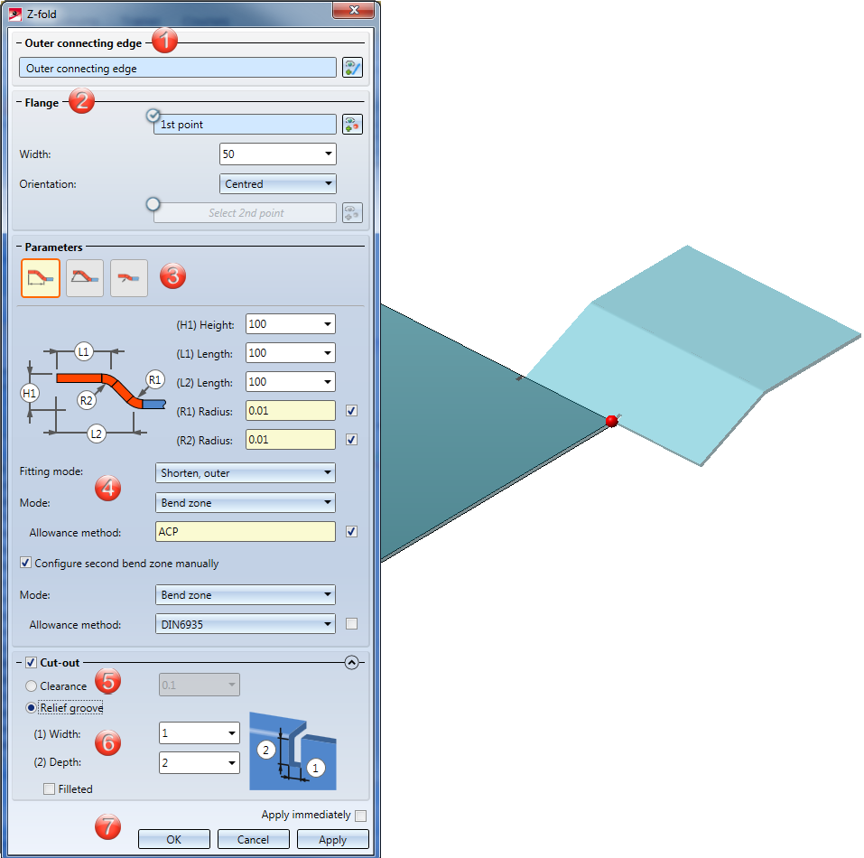
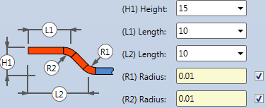
The new Z-fold function allows you to attach 2 flanges to a sheet with one single working step. As soon as your inputs are sufficient, a preview of the new flanges will be displayed. That is, if you choose a connecting edge, the possible Z-fold with the standard values will be displayed. If you have activated Width via point(s), the new flanges will only be shown after identifying a point and the width, or 2 points, provided that you have chosen the connecting edge. Furthermore, you will directly seethe change if, for instance, you switch from Shorten, outer to Shorten, inner. If the Apply immediately checkbox has been activated, the Z-fold will be immediately attached if the value inputs are sufficient and make sense, and can then be changed via the Feature log.
The selection of the connecting edge is decisive for the direction of the new Z-fold. After selecting the outer connecting edge, a preview of the new flanges will be displayed, provided that you have not activated any options that require further value inputs. If the Apply immediately option has been activated, the Z-fold will be inserted immediately. Changes can then be carried out the via Feature log.
If you want to identify a different edge, click on the  icon in the Outer connecting edge area and identify the edge.
If you activate the option for the 1st point  , the width of the new folding can be freely selected - irrespective of the connecting edge. After choosing the 1st point in your drawing, you can set the Width and the Orientation; alternatively, you can identify a second point. If you want to choose a different point selection, click on the
  icon and identify the point. If the points are located on an edge, this edge will become the connection edge, provided that you have not identified the connecting edge yet.
If you have activated the Relief groove option, the Fitting mode will only refer to the flange area. If the option has been deactivated, the Fitting mode (e.g. with shortening of the connecting flange) will refer to the complete connecting edge.
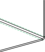
|
|
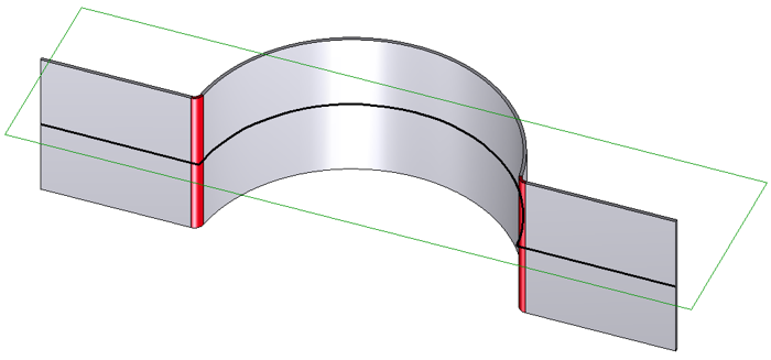
If this option has been chosen, you create the Z-fold by specifying Height and Length. The Radius is loaded from the semi-finished product in this example. Deactivate the checkbox
|
|
|
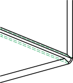
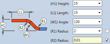
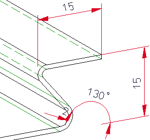
Here you define the Z-fold by entering an Angle. The first Radius here is entered manually, the second Radius will be loaded from the semi-finished product.
|
|
|
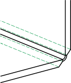
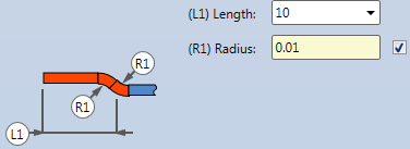
Here you create the Z-fold via an offset by the sheet thickness. The Radius will be loaded from the semi-finished product.
|
The Fitting mode determines the processing of the existing flange.
|
|
Shorten, outer The connecting flange will be shortened if you use this mode. The outer flange surface intersects with the plane of the front surface before the shortening. |
|
|
Shorten, inner The connecting flange will be shortened. The inner flange surface intersects with the plane of the front surface before the shortening. |
|
|
Without shortening The connecting flange will remain unchanged. |
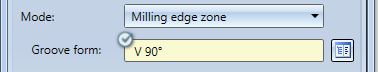
For the Mode option you can choose between Bend zone and Milling edge zone. Milling edge zones are in practice used for composite panels. If you choose Bend zone, you can subsequently assign an Allowance method. If you choose Milling edge zone, you can subsequently choose a Groove form.
For the Groove form you can choose the matching milling tool from the Composite panels, groove form catalogue  .
.
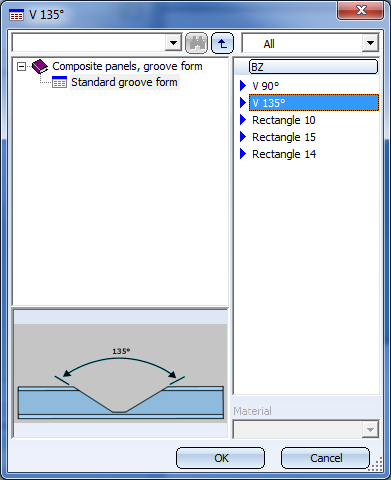
If you have activated the checkmark here, the tool will be assigned automatically.
A Clearance will be created if you attach a flange between 2 points, requiring a shortening of the connecting surface due to the fitting mode. If you right-click on the input field you have the option to pick the clearance from the drawing.
If the flange is larger or smaller than the connecting edge, and the fitting mode shortens the connecting edge, it make sense to insert a Relief groove. Enter a Width and a Depth for the relief groove.
After entering all required data you have the following options: If you click Apply or press the MMB, the new Z-fold will be inserted into your drawing, but the dialogue window will remain open, allowing you to make adjustments if required. If you click OK, the Z-fold will be inserted and the window will be closed. If you choose Cancel, the window will be closed and the specified settings will be discarded. If you have activated the Apply immediately checkbox, the parameters will be applied on the spot.
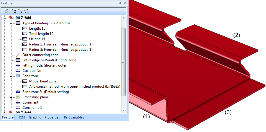
(1) Z-fold with length, height and Feature log
(2) Z-fold with angle, width via points and relief groove
(3) Z-fold with offset by sheet thickness
The Sheet along sketch function now also considers non-tangential transitions between a straight line and a an arc. Where the line bends, a bend zone or a milling edge zone will be inserted:
When using the Trim functions on flanges or planes you have now the option to enter a negative value for the clearance.
(1) Trimming the plane, Clearance 2 mm
(2) Trimming the plane, Clearance -2 mm
When performing bending simulations you can now also identify the edge for the base sheet in the sectional view or detail view. The bending simulation will then be performed in the original view. This will invalidate the sectional/detail view, which needs to be updated.
If you have selected an edge that was caused as a result of the cut, an error message will be displayed.
(1) Edge for base sheet
![]() Please note:
Please note:
The identification will not work if the sectional view has been created with the options Unfolded or Only cut surface.
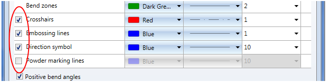
When you click on the Extended settings  button of the Sheet development parameters dialogue window and open the Edges and lines tab, you will now find new checkboxes for the element types Crosshairs, Embossing lines, Direction symbols and Powder marking lines.
If the respective checkbox has been activated, the parameters set here will be considered for development. If the checkbox is deactivated, the pre-setting will be used.
If two flanges abut when performing a development without clearance, a new line representing a separating cut will be inserted in the development. If the front surface of a bend zone directly abuts on a flange, here, too, a separating cut line will be inserted.
If you do not want to show separating cut lines between flanges, or between flanges and bend zones, deactivate the corresponding checkbox  Extended representation tab.
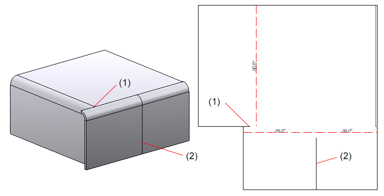
(1) Separation cut line between flange and bend zone
(2) Separation cut line between flanges
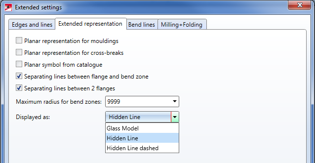
You can now select via the Sheet development parameters how a created development is to be displayed: Open the Extended settings dialogue window, go to the Extended representation tab and choose the desired representation from the Displayed as: selection list. The default value is Hidden Line.
The default setting for the sheet development and the changing of the Favourites also affects drawing derivations  for sheets, the export of developed sheets as DXF files
  and the settings in the Configuration Editor (Sheet Metal> Sheet development > Default setting).
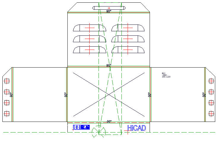
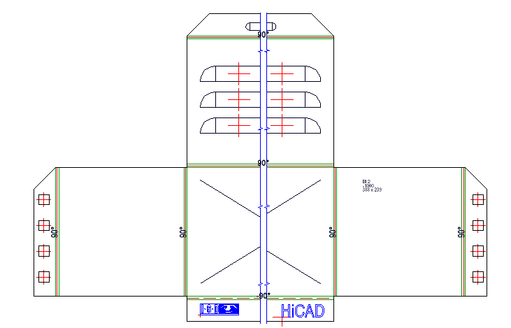
When milling composite panels the coated side is normally the bottom side. With the Invert upper side option you can rotate the upper side to the X- or Y-axis when creating the development.
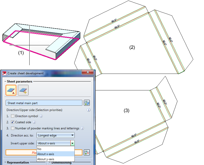
(1) Sheet metal main part
(2) Upper side inverted, rotated about Y-axis
(3) Upper side inverted, rotated about X-axis
The functions for data exchange of sheet developments have been enhanced. Besides DXF/DWG, XML and GEO you can now also export STEP files.
|
|
This function exports an individual development - either completely or as a section contour. |
|
|
|
Use this function to export the section contour or the complete development of Sheet Metal parts or Steel Engineering plates. In the process, a temporarily created development for the export will always be output. |
|
|
|
Use this function to export multiple developments with different parameter settings, e.g. LVD and Bystronic, of one or different Sheet Metal parts. |
For the export of STEP files you have the following options:
|
Transfer layers |
The layer on which the edge is located (e.g. bend lines on Layer 2) will be transferred during export. |
|
Transfer colours |
The colour will be transferred during export. If you have deactivated this option, you cannot use the Export fits information via surface colour option (see below). |
|
Export fits information via surface colour |
By activating or deactivating this checkbox you can determine whether fits information are to be exported by means of a surface colour. For this to happen, the Transfer colours checkbox (see above) needs to be deactivated. The diameter of the corresponding bore will then be highlighted in a different colour in the imported STEP part. In the SYS directory of your HiCAD installation you find the configuration file FITINFO_COLOR.DAT, in which it is determined which RGB value are to be assigned to which fits information. |
|
Export free points |
By activating or deactivating this checkbox you can determine whether the exporting of free points in the model drawing should be allowed or suppressed (if they could cause problems in other places). |
|
Export free edges |
By activating or deactivating this checkbox you can determine whether the export of free edges in the model drawing should be allowed or suppressed (if they could cause problems in other places). |
|
Thread body |
Choose As separate parts or United with parent part if you want thread bodies to be exported as individual parts or united with their superordinate part, respectively, in the model drawing. Choose Do not transfer if you do not want the thread bodies to be exported. |
When carrying out exports using the functions
a warning message will be displayed if older versions of referenced sheets exists.
If you use HCM constraints in conjunction with Sheet Metal parts, references will often refer to flanges or bend zones. In older versions, the reference was often displayed as "Sheet flange" or "Bend zone" in the HCM window of the ICN.
Now, such reference are always displayed as "Sheet Metal", i.e. the entire sheet.
The Processing direction  function is not only relevant for Sheet Metal parts, but also for identifying the installation direction of tray panels in the Element Installation module. Therefore, this function has been moved, to the Standard processings function group of the 3-D Standard Ribbon tab.
The bend radius and the allowance method can be taken from semi-finished products in the dialogue windows of the following Sheet Metal functions:
The value will be shown in the dialogue window.
The spelling of the punching tools (alias names) in the catalogue (at Factory standards) in HiCAD has been standardizes, which you will see when selecting the Punching tools function.
Sheets for Element Installation panels will now be assigned notchings that are suitable for production when applying the Cut off corner function.
When you choose the Lettering  function the last used settings will be shown in the dialogue window.
For sheets with agraffes, e.g. suspended ALUCOBOND® panels, the position of the agraffes will only be dimensioned in derived drawings if the Processings checkbox in the Sheet development default settings dialogue window has been activated. Agraffes will only be dimensioned if the Planar representation for mouldings checkbox in the Extended settings of this dialogue window has been deactivated. Start point and end point of the agraffe will be considered in the dimensioning of the outer contour.
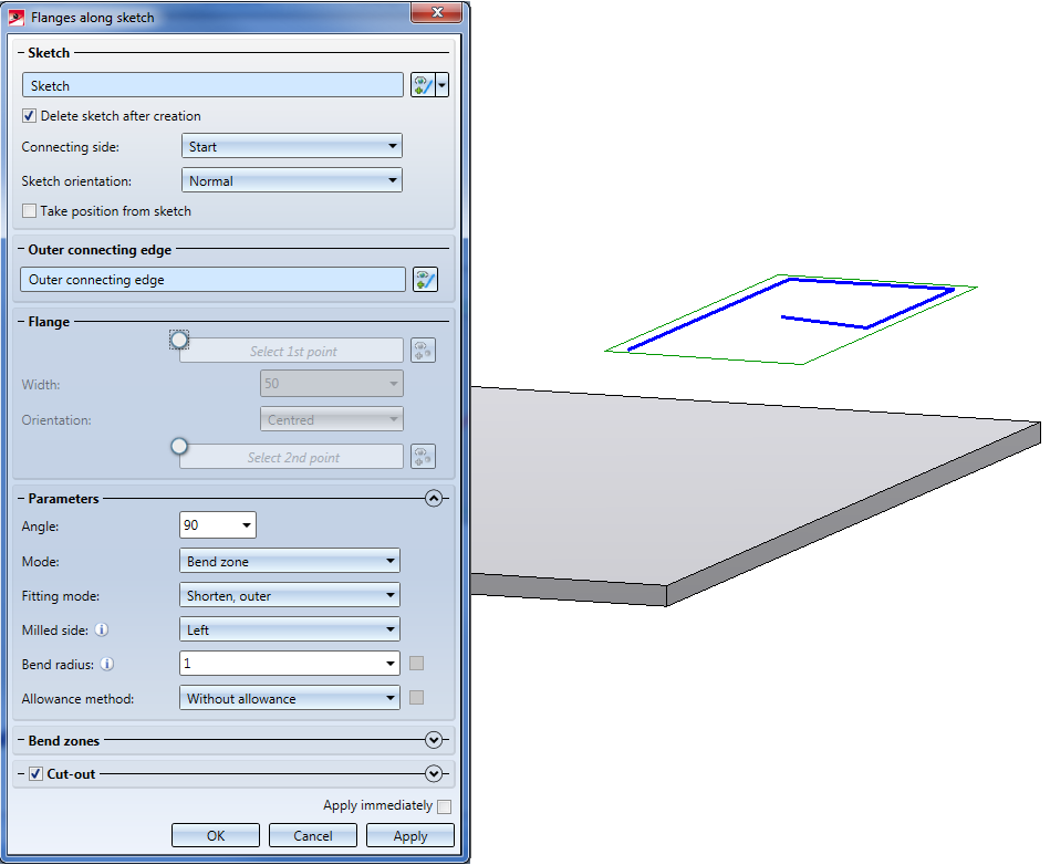
You can use the completely revised Flange along sketch function to attach several flanges to a sheet in one step. As soon as your value inputs are sufficient, a preview of the new flanges will be displayed, i.e. when you choose a sketch and a connecting edge, the possible flanges are will be shown on the Sheet Metal part. If you have activated Width via point(s), the new flanges will only be shown after identifying a point and the width, or two points, provided that you have selected the connecting edge. Furthermore, you can immediately see the change if, for instance, you switch from Shorten, outer to Shorten, inner. If the option Apply immediately is active, the flanges will be attached if the value input made sense, and can then only be changed via the Feature log.
You can also click on the  button at the top of the window and choose New sketch in plane
 to draw a new sketch using the Sketch functions. Then, click on the Apply sketch button. To change the sketch, click on the Process sketch
  button. This function can also be accessed via the button, The toolbar with the Sketch function and the dialogue window for Sketch processing will be displayed. When you end the processing of the sketch via the dialogue window you will get back to the Flanges along sketch dialogue window.
If you want to identify a different sketch, click on the icon in the Sketch area and chose the new sketch.
The selection of the connecting edge is decisive for the direction of the new flanges. After selecting the sketch and the connecting edge, a preview of the new flanges will be shown. If the Apply immediately option is active, the new flange will be inserted. Changes can then take place via the Feature log.
If you want to identify a different edge, click on the icon in the Connecting edge are and choose the different edge.
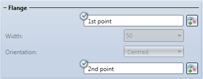
When you activate the option for the first point you can freely choose the width of the new flange, independently from the connecting edge.
After selecting the 1st point in the drawing, you can set the width and its orientation; alternatively, you can identify a 2nd point.
If you want to change the selected points, click on the icon for identification.
Here you enter the bend angle of the first new flange.
For the Mode option you can choose between bend zone and milling edge zone. The milling edge zone is used in practice for compound sheets.
For the milled side, which will only be evaluated if the milling edge zone mode has been chosen, the direction of the sketch is decisive. The setting is used as the default setting for the complete Sheet Metal part and can, in the Bend zones area, or via the Feature, changed individually for each milling edge zone.
The bend radius will only be evaluated if the Bend zone mode has been chosen.
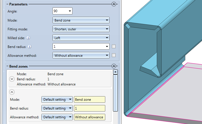
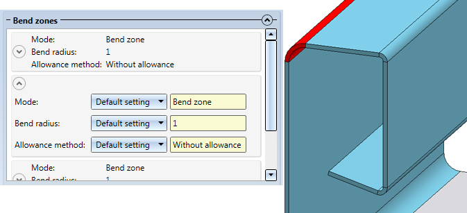
In the Bend zone area you can assign individual values to each bend zone.
In the expanded table you can choose between a bend zone or a milling edge zone for Mode. Depending on the chosen mode, you can then change the value for the bend radius or the milled side.
Depending on the processing type, the allowance method can be selected for each bend zone.
If the flange is smaller than the connecting edge and the fitting mode shortens the connecting sheet, it makes sense to insert a so-called relief groove. Enter the width, the depth and the type of the relief groove.
After completion of your data input you can attach the new flanges. If you click Apply or press the MMB, the flanges will be attached, and the dialogue window will remain open, allowing you to change the data and apply them to a different connecting edge. Clicking OK attaches the flanges and closes the dialogue window. Clicking Cancel discards your value inputs and changes, without attaching the flanges. If the option Apply immediately is active  , the data will be applied directly.
In many functions, the middle mouse button (MMB) cannot only be used to cancel a function (as long as the entered data has not been confirmed yet), but also to speed up design processes. For instance, after creating a new base sheet, you can directly apply the data you entered in the dialogue window to another base sheet by pressing the MMB, without having to open a new dialogue window and pressing the Apply button again. This is possible with the following functions:
To further improve the user-friendliness of the Sheet Metal tab, some functions were combined into new function groups and moved to the first, immediately visible level of the UI.
|
Sheet Metal functions |
|
|---|---|
|
Change length |
|
|
|
|
|
|
|
|
|
|
|
|
|
|
|
|
|
Sheet development |
|
|
|
|
|
|
|
|
|
|
|
Docking window |
|
|
|
|
The data exchange functions have been optimized further. With the following three functions you can output
|
Functions |
Description |
|
|---|---|---|
|
|
This function exports a development - either completely or as section contour if you have chosen the DXF/DWG output. Also, you can export the sheet developments from HiCAD as XML file for CADMAN-B (from Version 7.5 onwards) by LVD. A prerequisite for the output of LVD data is the assigning of bending tools to the bend zone with the Bend zone tooling If you have chosen GEO as output format, the development will be exported from HiCAD to the ToPs GEO file format. The GEO data can be directly loaded into the individual modules (Laser etc.) of the ToPs family. The configuration of the file name takes place via the file SheetToDXF.FTD. You can customize this file in the Annotation Editor if desired. If this does not result in a proper name, the name will be "Sheet". |
|
|
Export |
||
|
|
Use this function to export the section contour or the complete development of Sheet Metal parts or Steel Engineering plates if you have chosen the DXF/DWG output. In the process, a temporarily created development for the export will always be output. Also, you can export the sheet developments from HiCAD as XML file for CADMAN-B (from Version 7.5 onwards) by LVD. A prerequisite for the output of LVD data is the assigning of bending tools to the bend zone with the Bend zone tooling If you have chosen GEO as output format, the development will be exported from HiCAD to the ToPs GEO file format. The GEO data can be directly loaded into the individual modules (Laser etc.) of the ToPs family. The Close & Report button activates the Report Manager and creates a BOM. All attributes will be transferred to the Report Manager (as with drawing creation) and, additionally, the file name and the file path of the export. You can configure a RMS file with the Report Manager, determining which data are to be written. |
|
|
|
Use this function to export multiple developments with different parameter settings, e.g. LVD and Bystronic, of one or different Sheet Metal parts. You can choose between the following formats:
A prerequisite for the output of LVD data is the assigning of bending tools to the bend zone with the Bend zone tooling If you have chosen GEO as output format, the development will be exported from HiCAD to the ToPs GEO file format. The GEO data can be directly loaded into the individual modules (Laser etc.) of the ToPs family. The Close & Report button activates the Report Manager and creates a BOM. All attributes will be transferred to the Report Manager (as with drawing creation) and, additionally, the file name and the file path of the export. You can configure a RMS file with the Report Manager, determining which data are to be written. |
|
When carrying out DXF exports Sheet Metal > Sheet development > Export  > Sheets , glass panes will also be considered for export as of HiCAD 2019. If there are multi-layered glass panes, the individual glass layers will be exported.
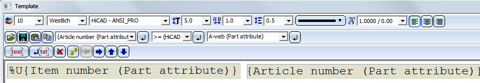
For annotation purposes and file name composition the attributes of the total glass pane can be used. In this context, please observe the information given in the Attributes of superordinate parts paragraph of the Attributes in annotation tags topic.
For instance, if you want the name of the DXF file to be composed of the item number of the complete pane and the article number of the glass pane, this can be achieved in the manual settings for the file name by using the following text blocks:
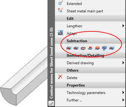
The context menu for bend zones has been expanded, now offering new Subtract and Divide functions. This allows you to apply straight cuts to or divide bend zones without having to switch to the functions on the 3-D Standard tab.
Right-click on a bend zone to open the context menu.
When attaching flanges a relief groove is now applied to the new flange if it projects beyond the connecting edge.
Collinear sheet edges can no longer be shown in the HiddenLine representation. Therefore, the following setting options have been removed:
For model drawings from 2018 and older you can no longer show collinear sheet edges in the HiddenLine representation. For these legacy drawings, the settings valid at the time of their saving apply. However, you have still the option to update the handling of collinear sheet edges in these legacy drawings to the new mechanism.
To do this, use the Update sheet edges  function. After applying the function you can hide collinear-tangential sheet edges in the HiddenLine representation if desired. Collinear bent edges will always be shown, while collinear mergeable edges will be hidden.
Bend zone texts will now be preserved in shortened views of sheet developments.
To improve user-friendliness, the user guidance texts for the lengthening of flanges and sheets in the info bar at the bottom left of the HiCAD screen have been revised.
Previously: 1st point; New: Vector of lengthening: Start point
Previously: 2nd point; New: Vector of lengthening: End point
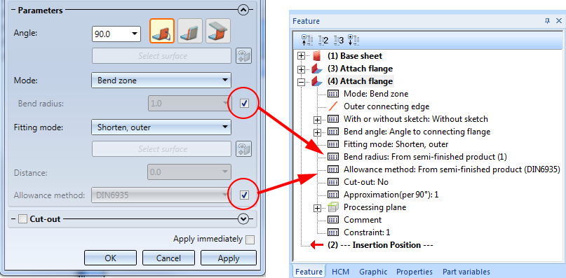
In some Sheet Metal function dialogue windows you can activate a From semi-finished product option for bend radius and allowance method. If you have selected these options, you can see the relevant value in the Feature log.
This is possible for the following functions:
From HiCAD 2019 onwards, continuous sectional views will only be generated in derived drawings if the bending edges run parallel or perpendicular to the view coordinate system.
In facade engineering Sheet Metal elements are often used in the form of bent profiles or tray panels. In such situation it is often desirable that these Sheet Metal parts are automatically dimensioned in the standard views (front/side/top views) when workshop drawings are generated, and that, in addition to the outer dimensions, processings will also be considered.
|
157 |
SHEETMETALBORES |
Bores in sheets |
|
158 |
SHEETMETALBORES_VERT |
Bores in sheets, perpendicular to view |
|
159 |
SHEETMETALOUTLINE |
Outer contours of sheets |
|
160 |
SHEETMETALBORES_SEPERATED |
Processings in sheets, dimension chains separated according to flanges |
|
161 |
SHEETMETALBORES_VERT_SEPERATED |
Processings in sheets incl. bores perpendicular to view, dimension chains separated according to flanges |
|
162 |
SHEETMETALOUTLINE_SEPERATED |
Outer contours of sheets, dimension chains separated according to flanges |
The sheet, complete with its flanges and bend zones, will be treated like one main part. A prerequisite for a working with these dimensioning rules is that an appropriate coordinate system has been defined with the functions beneath Alignment of derived drawings in the context menu of 3-D parts.

HiCAD Sheet Metal • General Notes on Sheet Metal Processing • Overview of Functions (3-D SM)
|
© Copyright 1994-2019, ISD Software und Systeme GmbH |


 to change the Radius.
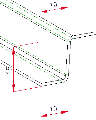


 .
.