Project: HiCAD Sheet Metal
Sheet Metal > Sheet development > Develop sheet
Use this function to create the 3-D development of a Sheet Metal part. You can choose between an automatic alignment of the sheet or an alignment via edges.
You can derive several developments with different parameter settings from one Sheet Metal part. The parameter settings will be saved with the development. For each development a new view will be created. The view and the Sheet Metal part are linked to each other. If the Sheet Metal part is deleted, the view of the development will also disappear.
You have the option to specify the development parameters during creation of the development. The functions for the changing of the parameters can be found at Sheet Metal > Sheet development > Update  > ... .
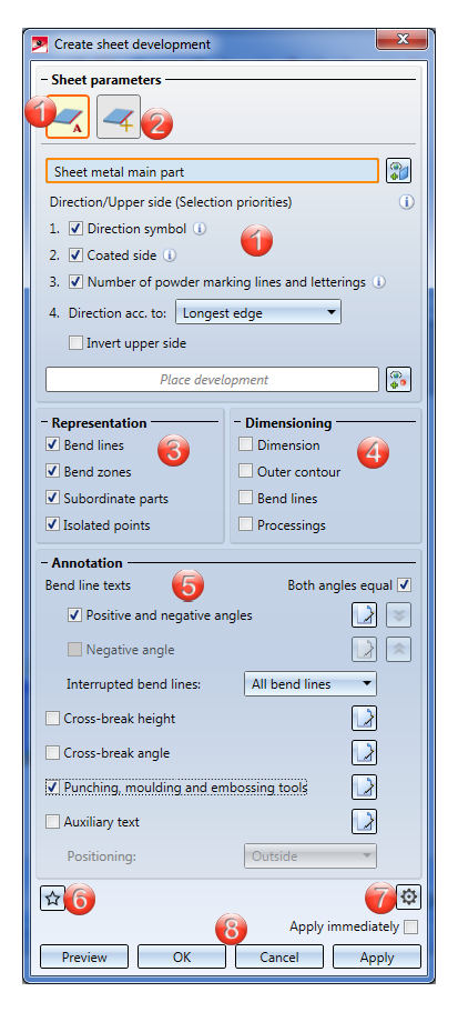
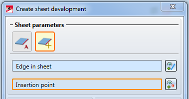
When you call the function, the following dialogue window will be displayed:
![]() Please note:
Please note:
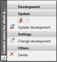
Right-clicking the development opens a context menu with processing functions:
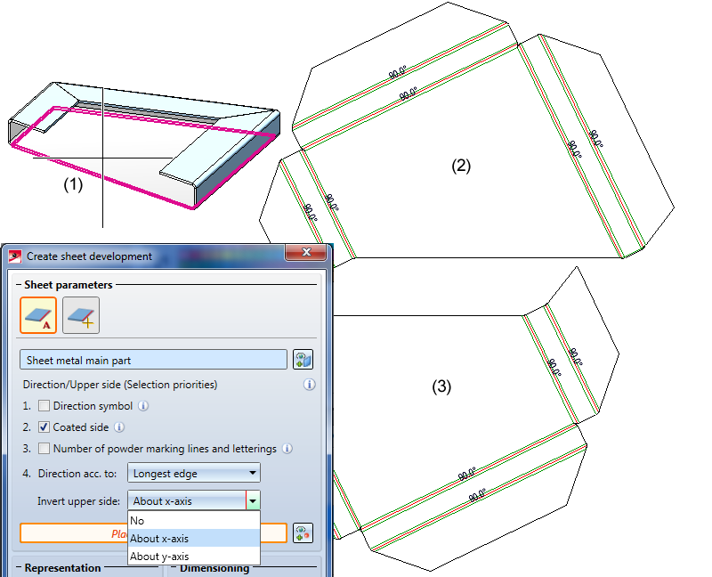
If you move the cursor over a text in the 3-D development, the text will be highlighted in magenta. If you now press and hold down the left mouse button you can move the text. When you update the development the text will be moved back to its original position.

To determine the alignment of the sheet automatically, click this icon  at the top of the Create sheet development dialogue window.
After identifying the sheet, a transparent preview of the 3-D development will be shown at the cursor. The options for the selection of direction and upper side (Direction symbol, Coated side, ...) can be changed by activating or deactivating the corresponding checkboxes. The priority results from the ascending order of the active options.
|
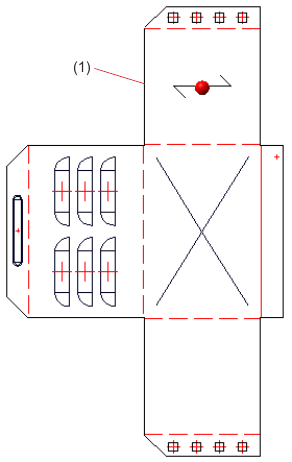
Direction symbol |
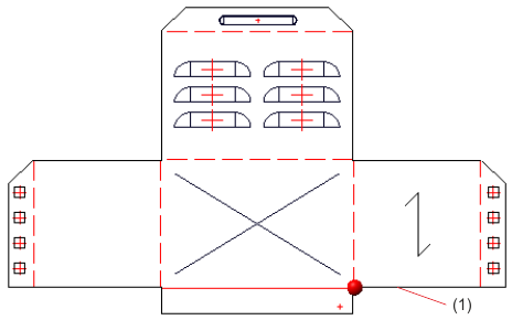
For instance, the direction symbol marks the processing direction and the processed side with a direction arrow. In this way, the development will be created from the side on which the arrow is located, and will be automatically aligned horizontally to the direction symbol. |
|
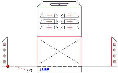
Coated side |
If the coated side is the upper side, the alignment will be horizontally to the longest edge or bend line, respectively. If both sides are coated, this option will not be evaluated. |
|
Number of powder marking lines and letterings |
If the upper side is determined by the number of powder marking lines and lettering, the alignment will be determined by the longest edge or bend line, respectively. |
|
Direction acc. to |
The development will be aligned horizontally to the longest edge or bend line, respectively. If no upper side has been selected, the upper side will be chosen at random if the option has been activated. |
|
Invert upper side |
When milling composite panels the coated side is normally the bottom side. With this option you can rotate the upper side to the X- or Y-axis.
(1) Sheet metal main part |
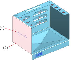
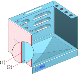
(1) Direction symbol
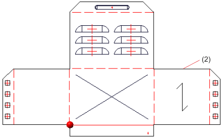
(2) Coating
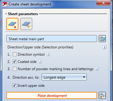
To determine the alignment of the sheet via the selection of an edge bordering on a top facet, click this icon  at the top of the Create sheet development dialogue window.
After identifying the sheet, a transparent preview of the 3-D development will be shown at the cursor. The identified edge determines the upper side and will be aligned horizontally in the development.
Upper side and alignment are determined by the identified edge
After entering all required data you have the following options: If you click Apply or press the MMB, the development will be inserted into your drawing, but the dialogue window will remain open, allowing you to make adjustments if required. If you click OK, the development will be inserted and the window will be closed. If you choose Cancel, the window will be closed and the specified settings will be discarded. Click Preview to update the development after making changes to the settings in the dialogue. For this to happen, the development must have been placed in the drawing.
If you have activated the Apply immediately  checkbox, the parameters will be applied immediately (provided that the value inputs make sense), allowing you to select a new Sheet Metal main part.
 Please note:
Incorrect or missing entries will be indicated by this symbol  . Moving the cursor over the symbol displays an explanatory text:

If the function cannot be executed on the basis of the entered data, this symbol  will appear on the OK button. Here, too, moving the cursor over the symbol displays an explanatory text:

If a sheet development cannot be correctly calculated, an appropriate error message will be issued. A disrupted calculation can, for instance, be caused by non-tangential transitions or edges between flange and bend zone.
The error message appears next to the OK button.
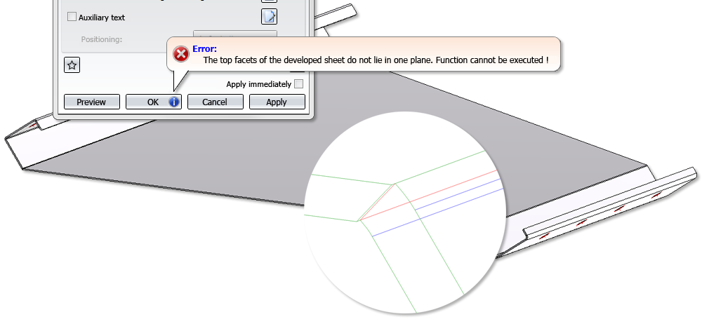
The blue edges are tangential edges(green (convex) and red (concave) edges are non-tangential edges).

Overview of Functions (3-D SM) • General Notes on Sheet Metal Processing (3-D SM) • Sheet Development (3-D SM) • Development Parameters (3-D SM) • Update Development (3-D SM) • Process Development (3-D SM)
|
© Copyright 1994-2019, ISD Software und Systeme GmbH |