
Project: HiCAD Sheet Metal
Sheet Metal > Process > Bending simulation
The Bending simulation function enables you to unfold complete sheet constructions into various levels for processing (e.g. bore). You can then bend the sheet back again. You can unfold several sheets at the same time. Identify the base sheets of the construction in turn.
You can also identify the edge for the base sheet in the sectional view or detail view. The bending simulation will then be performed in the original view. This will invalidate the sectional/detail view, which needs to be updated. If you have selected an edge that was caused as a result of the cut, an error message will be displayed. The identification will not work if the sectional view has been created with the options Unfolded or Only cut surface.
All sheets are bent towards the plane of the part identified as the base sheet.
You need to bend the sheets back individually. To bend the sheet part back, activate the Bending simulation icon once again and identify any sheet.
The sheet will be bent back into its original state.
(1) Base sheet
If a bending simulation cannot be correctly calculated, an appropriate error message will be issued. A disrupted calculation can, for instance, be caused by non-tangential transitions or edges between flange and bend zone. The bending simulation will, however, still be performed as far as possible
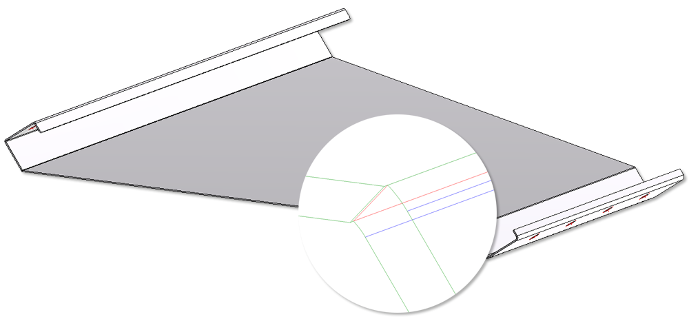
The blue edges are tangential edges(green (convex) and red (concave) edges are non-tangential edges).
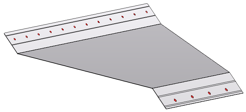

You can bore the sheet part in its developed state. The following drawing shows you which bores are valid and which not.
Valid bores
(1) Circular arc section
(2) Bend zone is divided
(3) Straight cut
(4) Skew cut
Invalid bores
(5) Flange is divided

|
© Copyright 1994-2019, ISD Software und Systeme GmbH |