Project: HiCAD Sheet Metal
Sheet Metal > Attach > Flange along sketch
You can use the Sketch functions to attach several flanges to a sheet in one step. As soon as your value inputs are sufficient, a preview of the new flanges will be displayed, i.e. when you choose a sketch and a connecting edge, the possible flanges are will be shown on the Sheet Metal part. If you have activated Width via point(s), the new flanges will only be shown after identifying a point and the width, or two points, provided that you have selected the connecting edge. Furthermore, you can immediately see the change if, for instance, you switch from Shorten, outer to Shorten, inner. If the option Apply immediately is active, the flanges will be attached if the value input made sense, and can then only be changed via the Feature log.
The areas of the dialogue window:

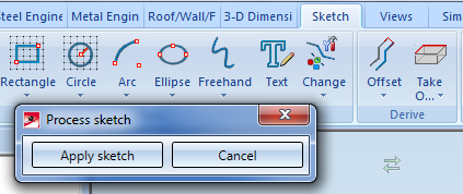
You can also click on the  button at the top of the window and choose New sketch in plane
 to draw a new sketch using the Sketch functions. Then, click on the Apply sketch button. To change the sketch, click on the Process sketch
  button. This function can also be accessed via the button, The toolbar with the Sketch function and the dialogue window for Sketch processing will be displayed. When you end the processing of the sketch via the dialogue window you will get back to the Flanges along sketch dialogue window.
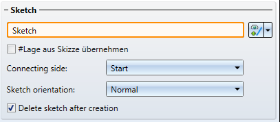
If you want to identify a different sketch, click on the  icon in the Sketch area and chose the new sketch.
|
Apply position from sketch |
You can only activate this function if the sketch touches the connecting edge and the sketch plane stands perpendicular to the front and top facet of the connecting flange.
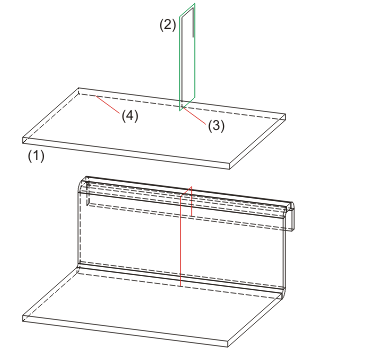
(1) Base sheet |
|
Connecting side |
Here you can choose whether the start point or end point of the sketch is to be attached to the connecting edge. |
|
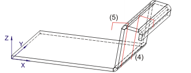
Sketch orientation |
The orientation of the sketch can either be Normal or Inverted.
(1) Sketch, normal |
|
Delete sketch after creation |
Activate this option if you want the sketch to be deleted from your drawing and the ICN after creating the flanges. |
The selection of the connecting edge is decisive for the direction of the new flanges. After selecting the sketch and the connecting edge, a preview of the new flanges will be shown. If the Apply immediately option is active, the new flange will be inserted. Changes can then take place via the Feature log.
If you want to identify a different edge, click on the icon in the Connecting edge are and choose the different edge.
![]() Please note:
Please note:
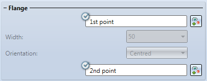
When you activate the option  for the first point you can freely choose the width of the new flange, independently from the connecting edge.
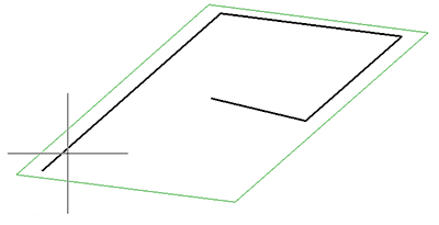
After selecting the 1st point in the drawing, you can set the width and its orientation; alternatively, you can identify a 2nd point.
If you want to change the selected points, click on the  icon for identification.
If the points lie on an edge, this edge will become the connecting edge, provided you have not identified a connecting edge yet.
If the Relief groove option has been activated, the fitting mode will be considered only in the area of the flange. If the option has been deactivated, the fitting mode (e.g. with shortening of the connecting edge) to the complete connecting edge.
|
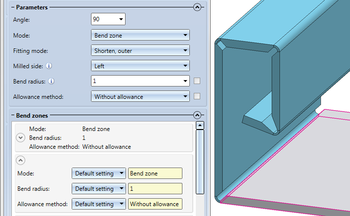
Angle |
Here you enter the bend angle of the first new flange. |
|
Mode |
Here you can choose between bend zone and milling edge zone. The milling edge zone is used in practice for compound sheets. |
|
Fitting mode |
The connecting edge will be shortened. The outer flange surface intersects with the plane of the front surface before the shortening.
The connecting edge will be shortened. The inner flange surface intersects with the plane of the front surface before the shortening. |
|
Milled side |
For the milled side, which will only be evaluated if the milling edge zone mode has been chosen, the direction of the sketch is decisive. The setting is used as the default setting for the complete Sheet Metal part and can, in the Bend zones area, or via the Feature, changed individually for each milling edge zone. |
|
bend radius |
The bend radius will only be evaluated if the Bend zone mode has been chosen. |
|
Allowance method |
To obtain the blank (development) of the modelled Sheet Metal part, HiCAD offers developments according to different calculations, the so-called "allowance methods", which take the material-dependent length changes of the workpiece during the bending process into account. HiCAD offers the practice-oriented, empirical allowance methods. A chosen allowance method is represented by a system file. A particular calculation method is represented by means of a system file. These files are prepared as examples, but in practice each user will store one or more of his own methods in this way. Before attaching the flanges, you can choose a system file here. In the Bend zones area you can assign a suitable allowance method to each flange. |
For instance, if you want to change the mode or the allowance method for a bend zone or a milling edge zone, click on the  icon to expand this area.
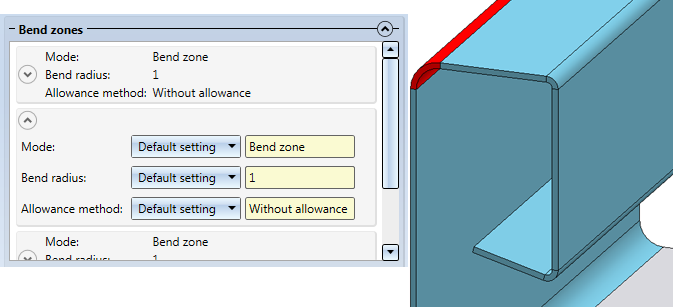
In the expanded table you can choose between a bend zone or a milling edge zone for Mode. Depending on the chosen mode, you can then change the value for the bend radius or the milled side.
Depending on the processing type, the allowance method can be selected for each bend zone.
A clearance is created if you attach a flange between 2 points and the connection surface needs to be shortened due to the fitting mode. If you right-click on the input field, you can pick a clearance from the drawing.

(1) Width of clearance
If the flange is smaller than the connecting edge and the fitting mode shortens the connecting sheet, it makes sense to insert a so-called relief groove. Enter the width, the depth and the type of the relief groove.

(1) Width
(2) Depth
(3) Filleted

The new flange obtains a relief groove if it projects over the connecting edge.
After completion of your data input you can attach the new flanges. If you click Apply or press the MMB, the flanges will be attached, and the dialogue window will remain open, allowing you to change the data and apply them to a different connecting edge. Clicking OK attaches the flanges and closes the dialogue window. Clicking Cancel discards your value inputs and changes, without attaching the flanges. If the option Apply immediately is active  , the data will be applied directly.
![]() Please note:
Please note:
Incorrect inputs are marked with the  symbol. If you move the cursor over the symbol, an error message will be displayed.

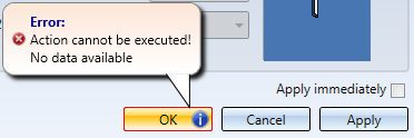
If the function cannot be executed with the entered data, the  symbol will appear next to the OK button. Move the cursor over the symbol to display an error message.

|
© Copyright 1994-2019, ISD Software und Systeme GmbH |