> Z-fold
Project: HiCAD Sheet Metal
Sheet Metal > Attach > Flange > Z-fold
The Z-fold function allows you to attach 2 flanges to a sheet with one single working step. As soon as your inputs are sufficient, a preview of the new flanges will be displayed. That is, if you choose a connecting edge, the possible Z-fold with the standard values will be displayed. If you have activated Width via point(s), the new flanges will only be shown after identifying a point and the width, or 2 points, provided that you have chosen the connecting edge. Furthermore, you will directly seethe change if, for instance, you switch from Shorten, outer to Shorten, inner. If the Apply immediately checkbox has been activated, the Z-fold will be immediately attached if the value inputs are sufficient and make sense, and can then be changed via the Feature log.
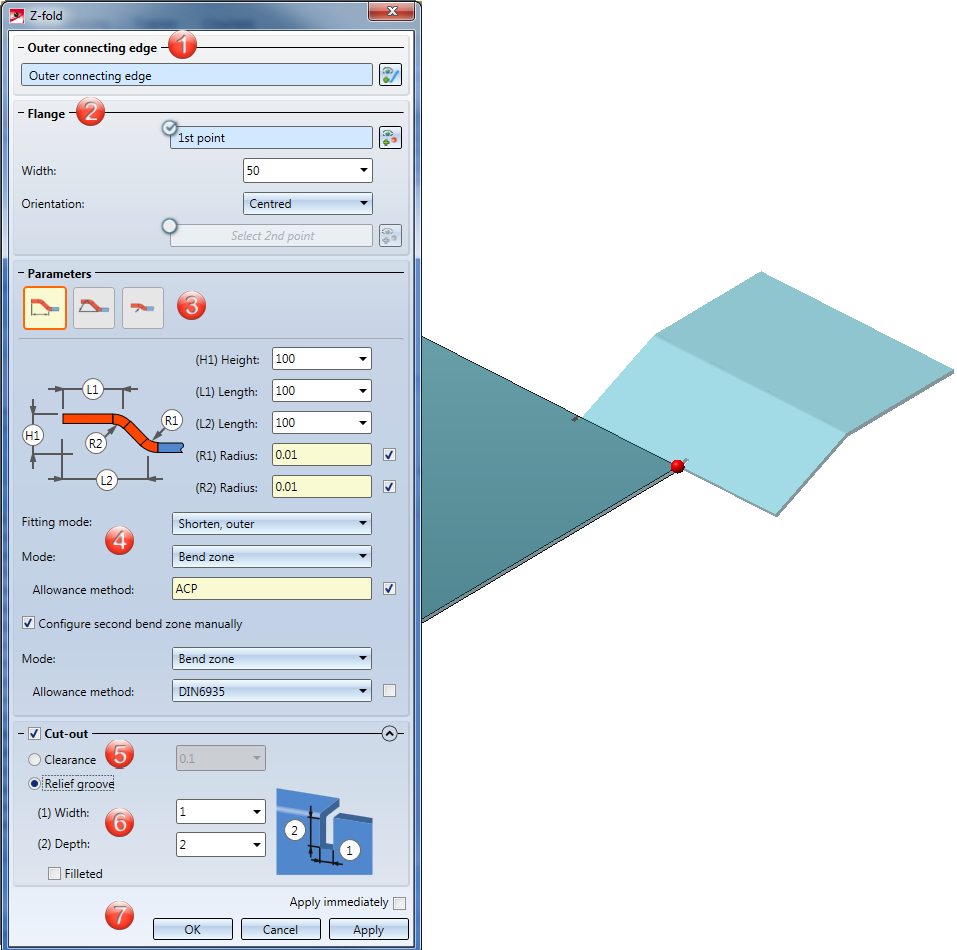
The Z-fold dialogue window consists of the following input areas:

The selection of the connecting edge is decisive for the direction of the new Z-fold. After selecting the outer connecting edge, a preview of the new flanges will be displayed, provided that you have not activated any options that require further value inputs. If the Apply immediately option has been activated, the Z-fold will be inserted immediately. Changes can then be carried out the via Feature log.
If you want to identify a different edge, click on the  icon in the Outer connecting edge area and identify the edge.
![]() Please note:
Please note:
If you activate the option for the 1st point  , the width of the new folding can be freely selected - irrespective of the connecting edge. After choosing the 1st point in your drawing, you can set the Width and the Orientation; alternatively, you can identify a second point. If you want to choose a different point selection, click on the
  icon and identify the point. If the points are located on an edge, this edge will become the connection edge, provided that you have not identified the connecting edge yet.
If you have activated the Relief groove option, the Fitting mode will only refer to the flange area. If the option has been deactivated, the Fitting mode (e.g. with shortening of the connecting flange) will refer to the complete connecting edge.
|
|
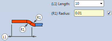
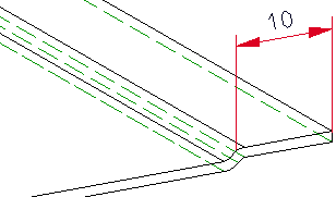
If this option has been chosen, you create the Z-fold by specifying Height and Length. The Radius is loaded from the semi-finished product in this example. Deactivate the checkbox
|
|
|
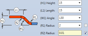
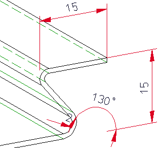
Here you define the Z-fold by entering an Angle. The first Radius here is entered manually, the second Radius will be loaded from the semi-finished product.
|
|
|
Here you create the Z-fold via an offset by the sheet thickness. The Radius will be loaded from the semi-finished product.
|
|
Fitting mode |
The connecting flange will be shortened if you use this mode. The outer flange surface intersects with the plane of the front surface before the shortening.
The connecting flange will be shortened. The inner flange surface intersects with the plane of the front surface before the shortening.
The connecting flange will remain unchanged. |
|||||||||
|
Mode |
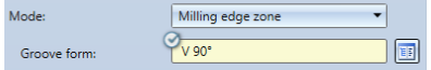
For the Mode option you can choose between Bend zone and Milling edge zone. Milling edge zones are in practice used for composite panels. If you choose Bend zone, you can subsequently assign an Allowance method. If you choose Milling edge zone, you can subsequently choose a Groove form.
|
|||||||||
|
Allowance method |
To obtain the blank (development) of the modelled Sheet Metal part, HiCAD offers you developments according to different calculation methods, so-called allowance methods, that allow material elongation to be taken into account during the bending process. HiCAD provides the empirical allowance methods that are used in practice. A particular calculation method is represented by means of a system file. These files are prepared as examples, but in practice each user will store one or more of his own methods in this way. You can choose a suitable allowance method for each Bend zone or Milling edge zone. |
|||||||||
|
Groove form |
For the Groove form you can choose the matching milling tool from the Composite panels, groove form catalogue
If you have activated the checkmark
|
A Clearance will be created if you attach a flange between 2 points, requiring a shortening of the connecting surface due to the fitting mode. If you right-click on the input field you have the option to pick the clearance from the drawing.
If the flange is larger or smaller than the connecting edge, and the fitting mode shortens the connecting edge, it make sense to insert a Relief groove. Enter a Width and a Depth for the relief groove.
After entering all required data you have the following options: If you click Apply or press the MMB, the new Z-fold will be inserted into your drawing, but the dialogue window will remain open, allowing you to make adjustments if required. If you click OK, the Z-fold will be inserted and the window will be closed. If you choose Cancel, the window will be closed and the specified settings will be discarded. If you have activated the Apply immediately checkbox, the parameters will be applied on the spot.
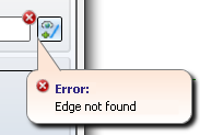
Incorrect inputs will be marked with the symbol. If you move the cursor over the symbol, an error message will be displayed.
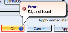
If the function cannot be executed with the entered data, the symbol will appear on the OK button. If you move the cursor over the symbol, an error message will be displayed.
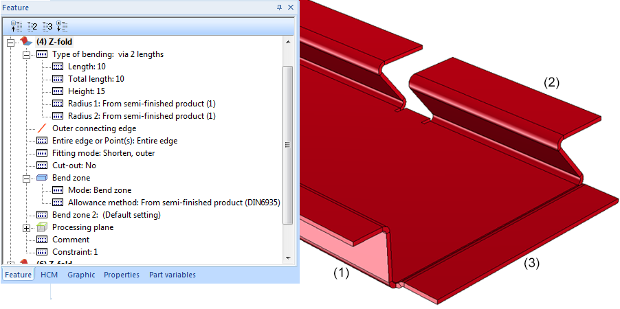
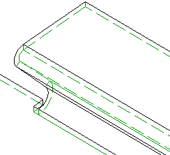
(1) Z-fold with length, height and Feature log
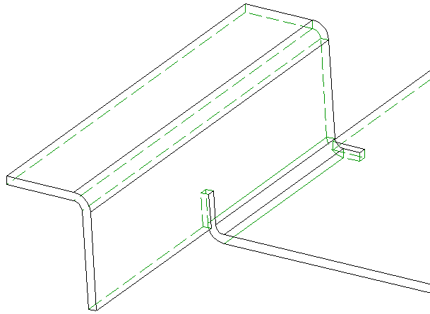
(2) Z-fold with angle, width via points and relief groove
(3) Z-fold with offset by sheet thickness
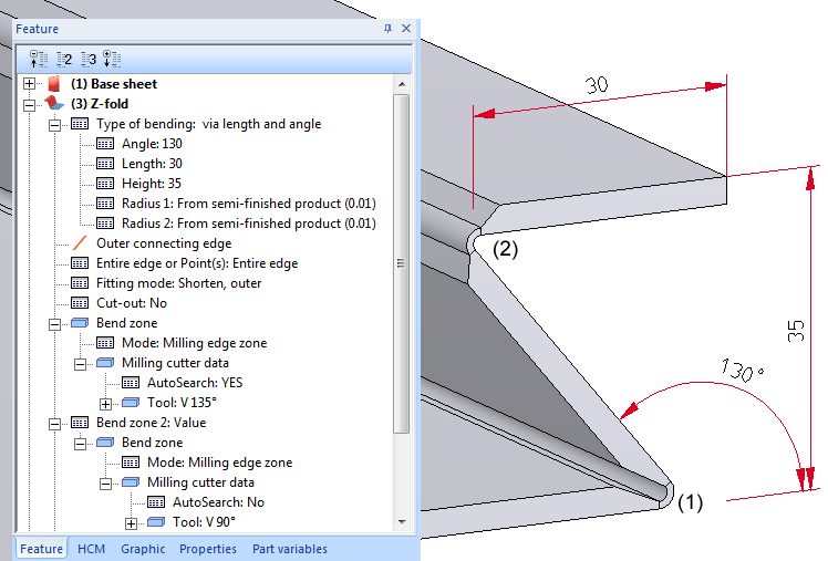
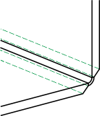
Z-fold with angle and milling edge zones
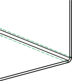
(1) Groove form V 135°
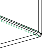
(2) Groove form V 90°

|
© Copyright 1994-2019, ISD Software und Systeme GmbH |

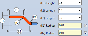
 to change the Radius.
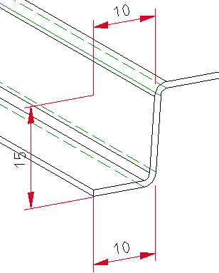


 .
. 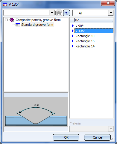
 here, the tool will be assigned automatically.