Project: HiCAD Sheet Metal
Sheet Metal > Further functions > Fold flange
Use the Fold flange function to fold 3-D Sheet Metal parts created from 2-D contours or existing Sheet Metal flanges subsequently. 3-D Sheet Metal parts can be created from 2-D contours with the New sheet from 2-D development function.
When you call the Fold flange function, the following dialogue window appears:

The dialogue window consists of the following areas:

The fold line is an arbitrary straight line in space which is projected onto the sheet. The fold line can be selected in two ways:
If you want to change the fold line after the after identification, click the  icon to renew the identification.
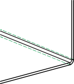
The Meaning determines the position of the fold line after the folding. The following options are available:
|
|
Bend line The fold line corresponds to the bend line in the sheet development.. |
|
|
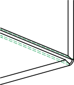
Cut, outer surfaces The fold line indicates the intersection point of the outer flange surfaces after the folding. |
|
|
Cut, inner surfaces The fold line indicates the intersection point of the inner flange surfaces after the folding. |
|
|
Outer tangent The fold line indicates the position of the outer bend zone surface after the folding. |
|
|
Inner tangent The fold line indicates the position of the inner bend zone surface after the folding. |
|
|
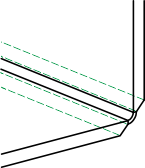
Bend zone border The fold line indicates the border of the bend zone on the side that is not folded. |
You specify the area to be folded by selecting an edge (e.g. to the left or to the right of the fold line). This edge is, while also taking the bend angle into account, decisive for the direction of the new flange.
After specifying the area to be folded, a preview of the new flange will be displayed (provided that you did not activated any options requiring further action).
If you want to change the area to be folded, click the  icon for identification.
If the Apply immediately option has been activated, the new flange will be inserted. Changes can be applied via the feature log.
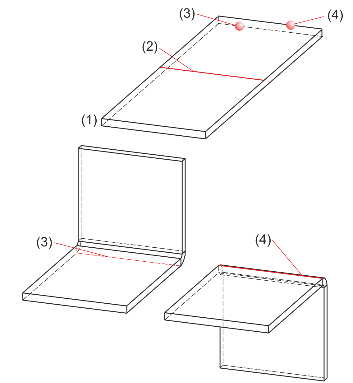
(1) Sheet
(2) Fold line
(3) Example: Area to be folded (edge on side to be folded)
(4) Alternative edge for area to be folded (edge on side to be folded)
The so-called bend angle is the angle about which a flange is folded. You can also enter a negative angle if desired. This angle will then only be shown in the feature; the bend angle that is saved on the bend zone is always positive.
The following options for angle input are available:
|
|
Angle input Folds the flange according to the entered angle. |
(1) Connecting edge |
|
|
Parallel to plane Folds the flange parallel to a selected plane |
(1) Connecting edge |
|
|
Perpendicular to plane Folds the flange perpendicular to a selected plane |
(1) Connecting edge |
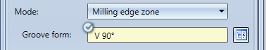
Composite sheets, such as ALUCOBOND panels, are folded along milling edges. The resulting milling edge zones differ geometrically from the cylindrical bend zones. Therefore, the Fold flange function offers the additional option to choose milling edge zones and milling tools.
The following options are available:
|
|
Bend zone The bend zone has the specified bend radius. |
|
|
|
Milling edge zone Bend zone with the selected tool (milled inside). |
|
|
|
Milling edge zone inverted Bend zone with the selected tool (milled outside). |
|
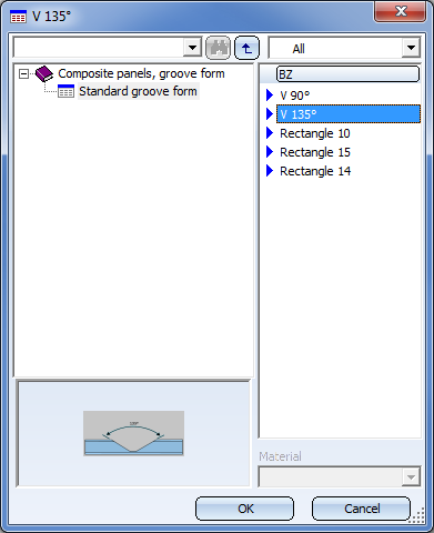
You can choose the desired milling tool from the Composite panels, groove form catalogue by clicking on the  Via catalogue symbol next to the right of the Groove form field.
The bend radius refers to the inner side of the bend zone. It will only be requested if you have chosen Mode: Bend zone. If the flange to be folded is a semi-finished product, you can take over the bend radius from the semi-finished material by activating the corresponding checkbox  .
.
You can also activate/deactivate or change semi-finished products subsequently. To do this, double-click, for instance, the Fold flange feature. The same-named dialogue window will then be displayed, where you can activate or deactivate the Use semi-finished product checkbox, or click the icon to choose a different semi-finished product. Confirm with OK to apply the settings.
The Allowance method filed will only be visible if you have selected Mode: Bend zone. During development, the bend zone are transformed into a plane and stretched additionally. The reason for this is the taking into account of the material expansion during bending. Therefore, HiCAD offers the empirical allowance methods which are commonly used in practice.
If the sheet is a semi-finished product, you can take over the data from the catalogue by activating the corresponding checkbox .
After entering all required data, you can insert the new flange.
If you click Apply or press the MMB, the flange will be inserted, and the dialogue window will remain open. If desired, you can then still change the data and apply it to a different area to be folded.
If you click OK, the flange will be inserted, and the window will be closed.
If you click Cancel, the window will be closed, and the function will be cancelled, without inserting the flange or changing the data. If you have activated the Apply immediately checkbox, the data will be directly applied.
 Please note:
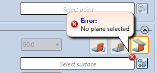
Incorrect or missing data inputs will be indicated by the  symbol. Move the cursor over the symbol to view the error message.
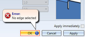
If the function cannot be executed with the entered data, the  symbol will appear next to the OK button. Move the cursor over the symbol to view the error message.
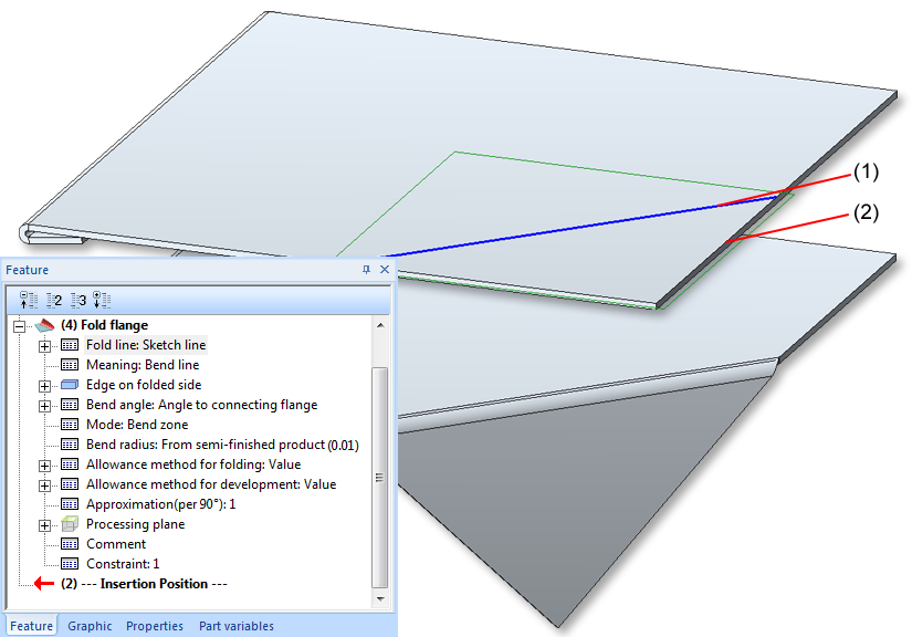
(1) Fold line with leading sketch
(2) Edge on side to be folded
In the feature log, the fold line (1) will be offered for processing.
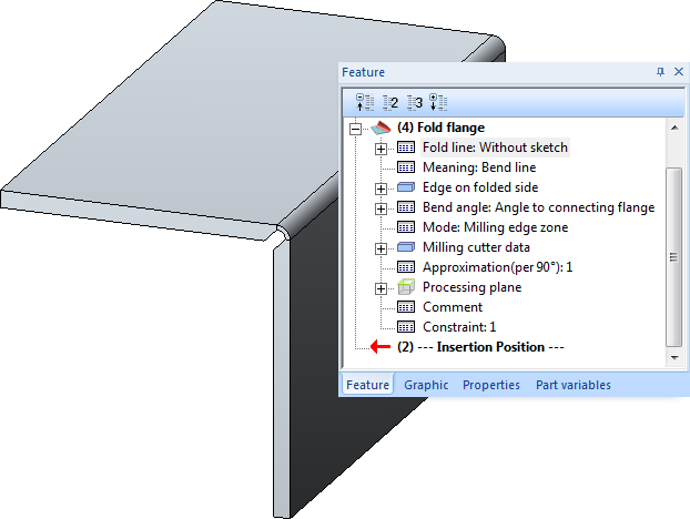
Folding with milling edge

Further Functions (3-D SM) • Attach Flange (3-D SM)
|
© Copyright 1994-2019, ISD Software und Systeme GmbH |