
Project: HiCAD Basics
Discontinuation of Windows 7 ®
Microsoft will cease the support for Windows by January 2020. Due to compability matters HiCAD 2020 SP2 and HELiOS 2020 SP2 will thus be the final versions of our CAD and PDM systems which support Windows ® 7. The corresponding server operating systems (Windows Server 2008 R2 or older) will then no longer be supported either.
Discontinuation of “old“ HiCAD itemisation
As of HiCAD 2019 the “old” itemisation, i.e. the itemisation that was used up to HiCAD 2017, will only be available for model drawings that were already itemized with these functions. From HiCAD 2020 onwards, only the “new” itemization will be supported. The itemisation by assemblies (the Within assembly, ... options in the old Itemisation dialogue) will only be supported by the new Standard Itemisation as of HiCAD 2019 SP2.
In test cases, the following performance optimisations (duration in seconds) could be achieved for switching the drawing to an empty one:
|
HiCAD 2302 |
HiCAD 2402 |
|
|---|---|---|
|
Example drawing with 4,800 parts |
10 |
5 |
|
Parametric drawing with 3,400 parts |
16 |
1 |
Which performance increase is ultimately achieved depends on the respective drawing.
The Visual Effects docking window has been renamed to Panoramas.
From HiCAD 2019 SP2 the ICN representation of up to three user columns is supported for the 3-D part structure. The representation can be switched on/off by activating/deactivating the checkbox.
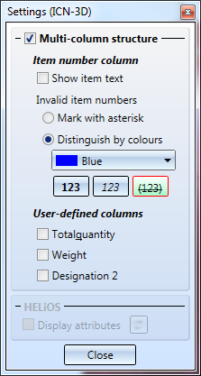
The attributes displayed in the three user columns can be configured individually. The user columns are defined in the HDB files ICN3D_USERn.HDB (for use without HELiOS) or ICN3D_USERn_DB.HDB (for use with HELiOS). n is the number of the user column. The files are located in the HiCAD sys directory.
The following user columns are predefined by ISD:
|
User column |
Attribute |
File without HELiOS |
File with HELiOS |
|
|---|---|---|---|---|
|
1. |
%06 |
Total number |
ICN3D_USER1.HDB |
ICN3D_USER1_DB.HDB |
|
2. |
§01 |
Weight |
ICN3D_USER2.HDB |
ICN3D_USER2_DB.HDB |
|
3. |
$02 |
Designation 2 |
ICN3D_USER3.HDB |
ICN3D_USER3_DB.HDB |
For instance, the number of the shipping item, that is, the item number of the uncut installation profiles (attribute %PI), plays an important role in installation planning. However, the item number (attribute %02) is important for substructures. By defining corresponding user columns, you can display both item numbers in different columns.
To change the default setting of a user column, click on the corresponding HDB file, e.g. the file ICN3D_USER1_DB.HDB for the first user column:
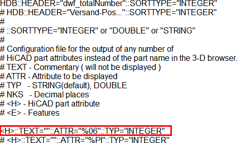
The row highlighted in red defines the contents of the first user column. The ISD default setting is the attribute %06, i.e. the total number. You can also enter the line more than once and mark the other lines as comments by placing the character # at the beginning of the line. In the file shown above, this is already applied for the attribute %PI, i.e. for the number of the shipping item. For example, you could delete the comment character in the %PI line and place it before the %06 line instead. The shipping item number would then be displayed in the ICN in the first user column.
See also HDX- und HDB-Dateien and Overview of HiCAD Attributes
When saving HDB files, please make sure that ANSI is selected as character encoding.
In the Settings of the 3-D ICN you can define how invalid, i.e. not current, item numbers are to be marked:
with an asterisk * or
Please note that item numbers with no current status are only marked accordingly the parameter Set change mark when changing parts is active in the Configuration Management under Compatibility > Itemisation up to HiCAD 2017 > Updating.

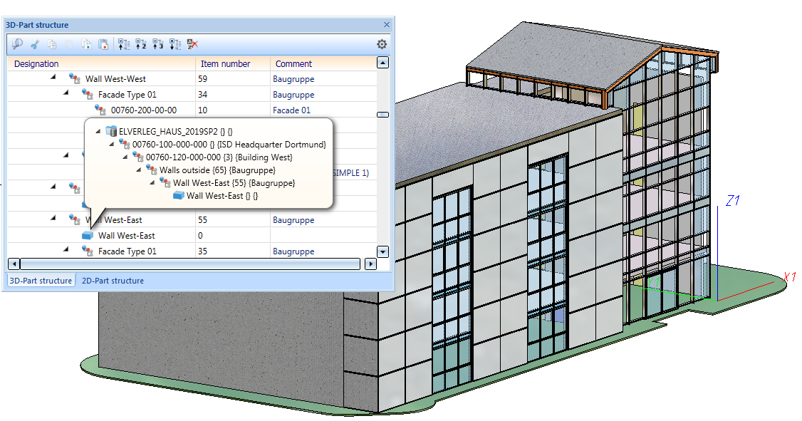
If you point to a part symbol in the 3-D part structure of the ICN with the cursor, now a tooltip with the corresponding superordinate structure is displayed. This can be especially helpful in large drawings with many parts.
The Part attributes dialogue window can be opened now by double-clicking on a part name with the left mouse button.
With the Surface Approximation  you define the number and determination of polygon points for 3-D quadrants. This setting is used, for example, when approximating polyhedra and shading 3-D models.
As of SP2, the ISD default settings in Configuration Management under Modeling > Part creation > Polyhedron approximation have been changed as follows:
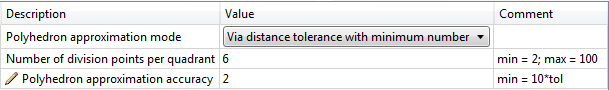
The settings shown above are also used in the Configuration Templates (CSV files) for mechanical engineering and plant engineering included in the scope of delivery of HiCAD, which are loaded via the Parameter Configuration. The steel/metal configuration template uses 4 division points per quadrant.
In the Settings for Conventional Dimensioning  for drawing derivation with regard to Bores/Boltings, the ISD default setting for Multiple display of successive, identical dimension chains if distance greater thanhas been changed from 30 to 1500. This has led to better results in practice.
 The customer settings are preserved during update installations. If you want to use the new value as the default setting, you must change the file STAB3DPAR.DAT accordingly or - if available - the file STW_DIMSETTINGS.XML (parameter SUMUPEQUALDIST). Both files are located in the HiCAD sys directory.
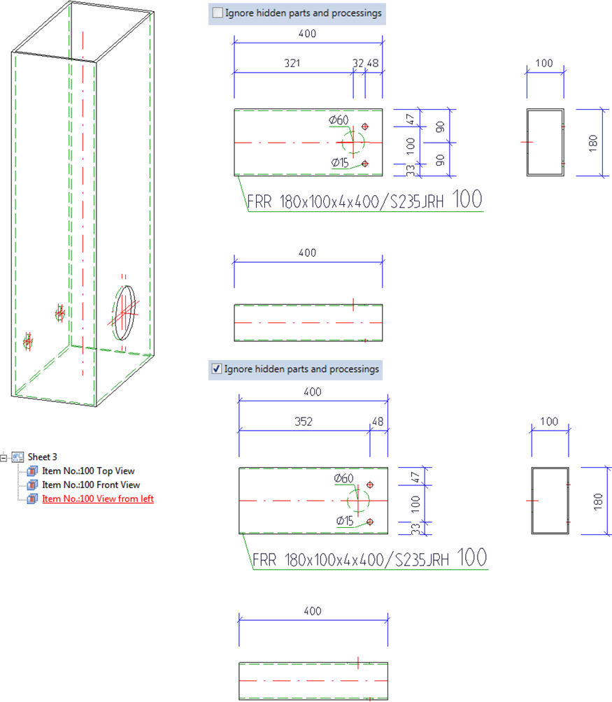
In the settings for "conventional" dimensioning, as of SP 2 it is possible to specify whether hidden parts and processings should be ignored. The setting predefined by ISD is no. This corresponds in the file STW_DIMSETTINGS.XML to the line </PARAM><PARAM Name="IGNOREHIDDENSUBPARTANDBORES" Typ="INT" Value="0"> or in the file STAB3DPAR.DAT (new customers) to the entry ignore base points on invisible parts and bores? 1:yes, 0:no
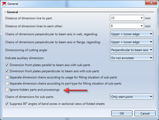
Please note that for drawing derivation this setting is only taken into account if the option Load drawing parameters from configuration is active.
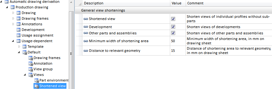
In the Settings for Views window the texts for shortenings in drawing derivation have been improved.
| Previously |
From HiCAD 2019 SP2 onwards |
|---|---|
|
Show views of beams as shortened views |
Beams as single part without sub-parts |
|
Show views of development as shortened views |
Developments |
|
Show other views as shortened views |
Other parts and assemblies |
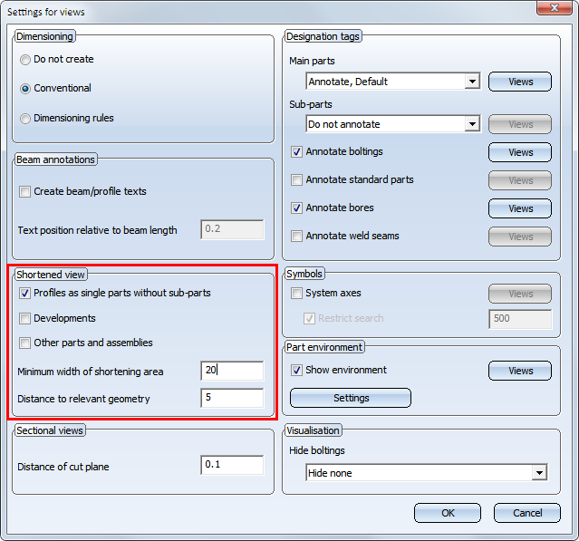
The corresponding texts in the configuration management (Automatic drawing derivation > Production drawing > Usage-dependent > ... > Views > Shortened view) have been modified analogously.
The HiCAD parameter configuration for steel/metal engineering has been changed. The objective was to make workshop drawings in steel engineering easier to understand. For more information, see Steel Engineering - What's New.
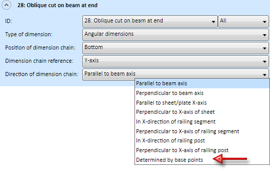
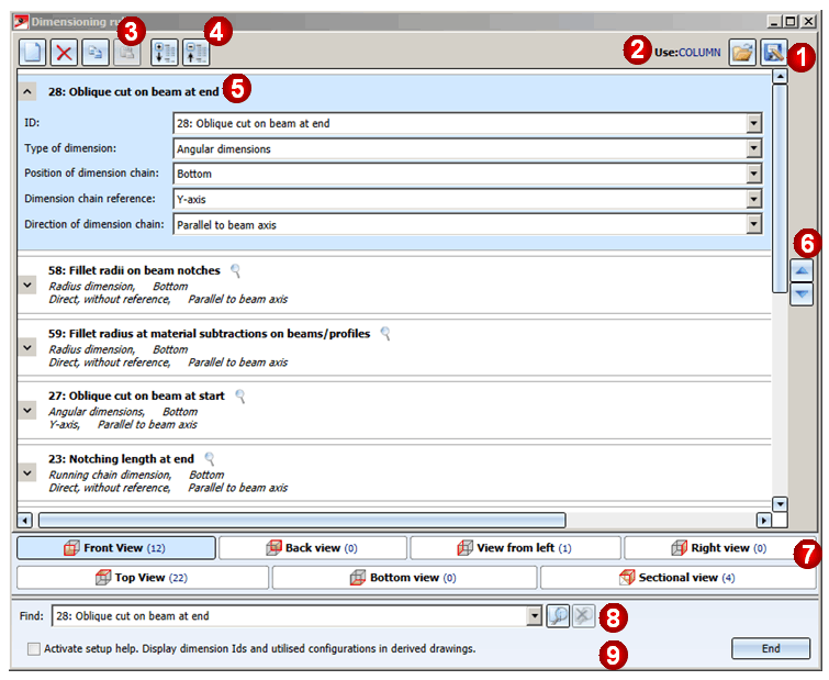
In the Dimensioning Settings, the Direction determined by 2 points option has been renamed to Determined by base points in the Direction of dimension chain selection box.
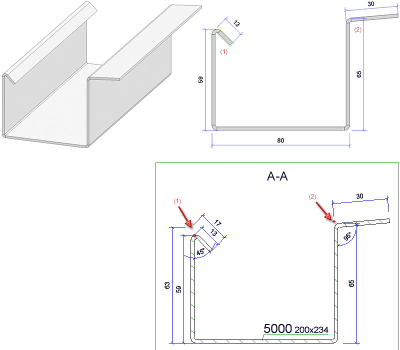
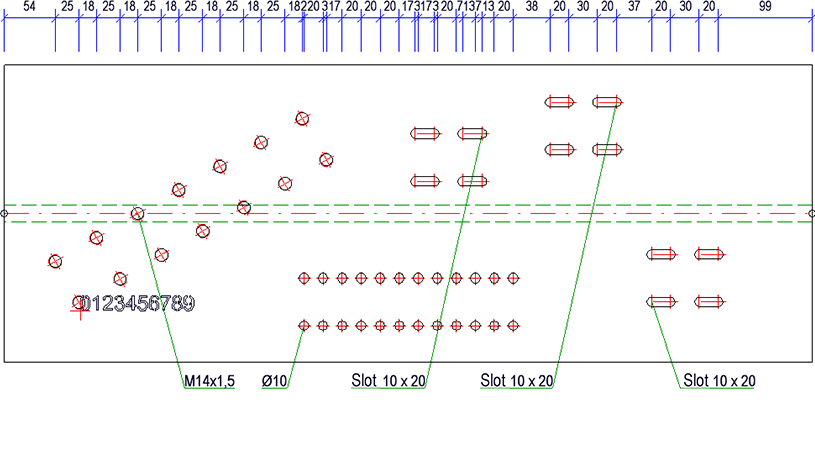
For dimensioning the flange length of sheets in sectional views, the following base point is being dimensioned:
at an initial angle > or equal to 90°, the theoretical intersection of the flanges; and
at an angle > 90° the tangential point at the edge of the bending zone.
The following graphic shows an example. The flange (1) was attached with an angle of 135°, the flange (2) with an angle of 85°. In the sectional view, the tangential point is dimensioned for flange (1) and the theoretical intersection point is dimensioned as the base point for tab (2).
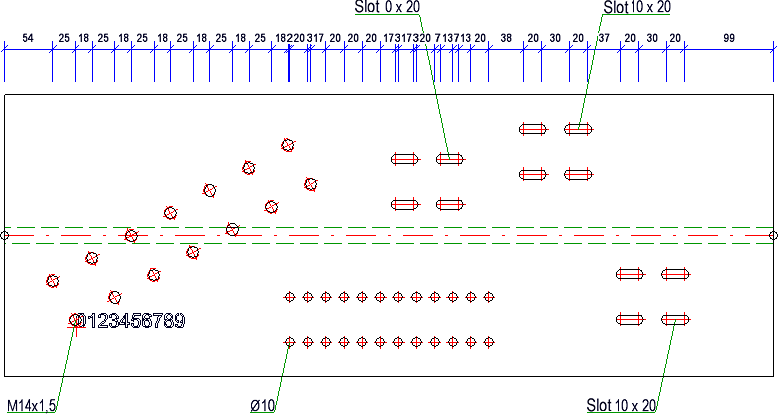
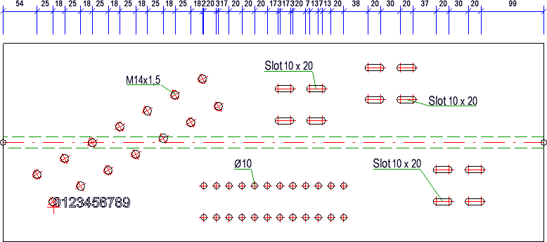
So far, the automatic placing of annotation for standard processings, e.g. threads, has often resulted in the leader line running unnecessarily across the hole bore pattern. This behaviour has been changed with HiCAD 2019 SP2. Now, the leader lines of standard processings always go to the nearest standard processing. In addition, the annotations can now also be placed on the part and not just outside as before. This applies to both production and mounting drawings. The settings are made via Configuration Management. There you can find via
the parameter Standard processing on part.
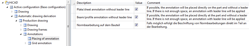
If the checkbox is active, the annotations of standard processings are located directly aside the processing - i.e. on the part - if there is enough space. If there is not enough space, the annotation is placed further away.
If the checkbox is inactive, the annotations are - as before - placed outside the part. The leader lines now always go to the nearest standard processing.
An example:
The Automatic drawing derivation function supports creating usage-dependent production drawings. Thus, individual dimensioning rules can be specified for different usages, such as girders, columns, certain beams, railings etc.By contrast, the creation of mounting drawings is being independent of the usage for parts and assemblies. Only the selected box is taken into account. In most cases this option is sufficient - the essential parts can be annotated automatically and grids can be dimensioned automatically as well.
However, in order to enable overall drawings with automatic creation of relevant dimensions for substructures of the element installation, dimensioning rule sets can also be defined in the Configuration management for mounting drawings - albeit to a very limited extent.
Hence, only three IDs are available:
These dimensioning rule sets can be used to define what is dimensioned and how (dimension type, position, reference, etc.) and in which view.
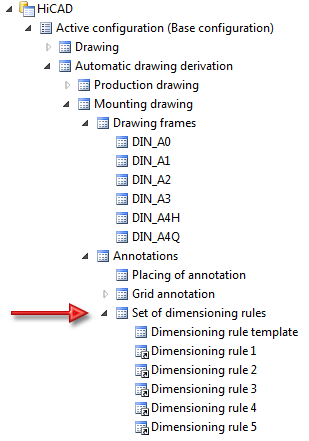
The following settings are recommended for sub-structures:
Dimensioning rule 1
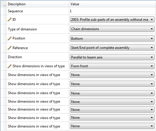
Dimensioning rule 2

Dimensioning rule 3
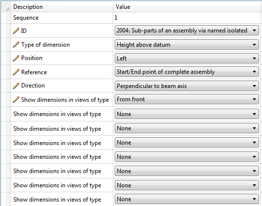
Tip for sub-structures/consoles:
When configuring the assemblies with wall consoles, you have the option to define a dimensioning-relevant point on the console assembly yourself. This point will be considered as decisive point (ID 2004). This decisive point must be a designated point, e.g. with the name !.
Please also take note of the hints in the area of Sub-structure.
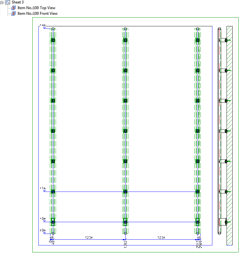
An example:
The illustration shows a substructure with wall brackets (and dimensioning-relevant relevant point)

If the mounting drawing is created with the settings listed above, the following example may result:
The basic settings for sheet metal processing, which were previously defined in the ABWPARDAT and ABWCOL.DAT file, can now be set in configuration management. For detailed information, see Configuration Management - What's New.
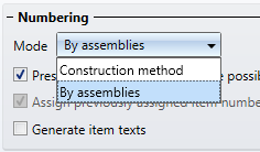
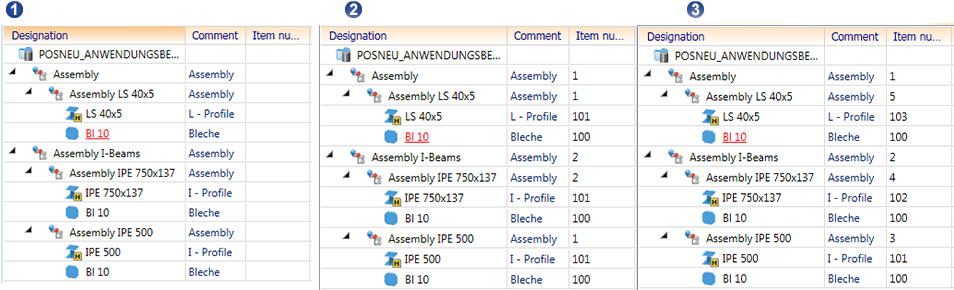
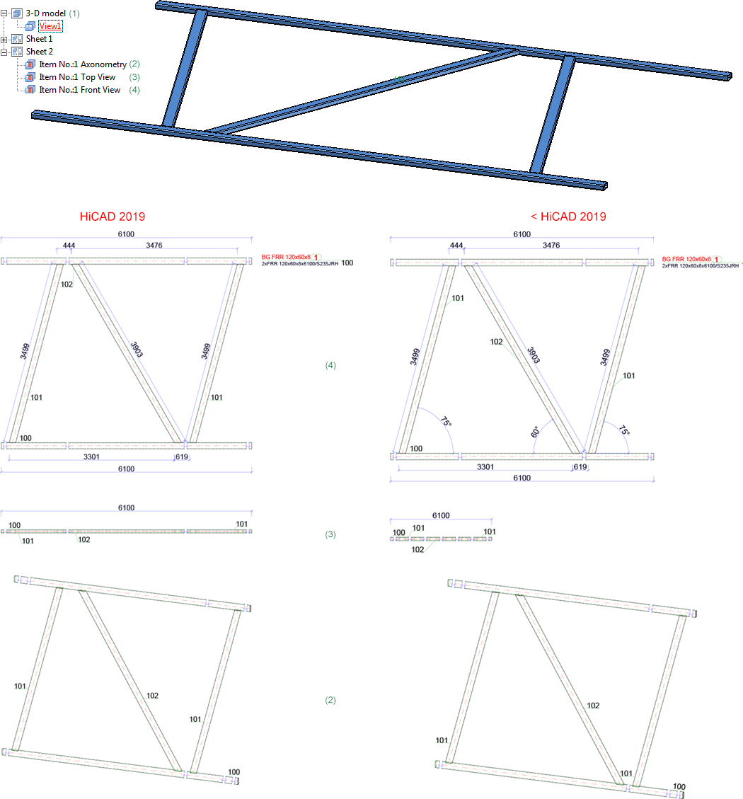
As of SP2, HiCAD supports itemisation by assemblies with its new standard itemisation. For this, the tab General has been enhanced accordingly. Under Mode, you can now select whether the itemisation is to be continuous for the entire design or continuous within an assembly.
Example
In the following illustration, the factory settings have been used for the steel engineering.
(1) Without item numbers, (2) Itemised in the mode By assemblies, (3) Itemised in the mode Construction method
As of HiCAD 2019 SP1, the Processing direction can also be selected as a distinguishing criterion for the search of identical parts. Previously, this option was only available for sheet metal plates. From SP2 onwards, steel plates are now supported as well.
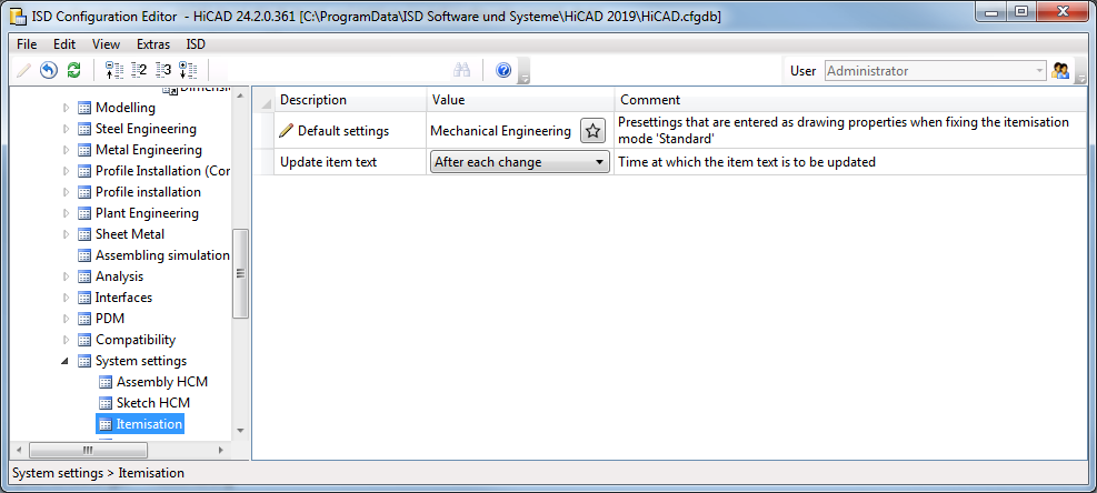
Previously, item texts were updated after each modification to drawings. In large drawings, this can lead to performance loss, especially if attributes from superordinate assemblies are used in item texts. For this reason, the new parameter Update item text is from SP2 onwards available under System settings > Itemisationto set the time for updating item texts.
Please note, however, that the setting After itemisationhas the disadvantage that it is not possible to recognize whether an item text is invalid.
The previous functions
 Information, Direct distance 2 points (3-D)
 Information, X-distance 2 points (3-D)
 Information, Y-distance 2 points (3-D)
 Information, Z-distance 2 points (3-D)
 Information, XYZ-distance 2 points (3-D)
have been combined to one function Information, distance 2 points (3D). The PullDown menu is therefore no longer used from SP2 onwards.
From SP2 onwards, new icons are available for different HiCAD file formats, such as SZA, FGA, KRA, VAA, PAA. These icons are taken into account in Windows Explorer and thus also in HELiOS result lists.
|
|
File format |
File type |
|---|---|---|
|
|
.SZA |
HiCAD drawing |
|
|
.KRA |
HiCAD 3-D part |
|
|
.FGA |
HiCAD 2-D part |
|
|
.VAD |
HiCAD variant of previous versions |
|
|
.VAA |
HiCAD variant |
|
|
.PAA |
HiCAD part archive |
|
|
.RPA |
HiCAD P+ID scheme |
|
|
.FIA |
HICAD P+ID module |


The function New support request is now available in Help Topics and Information 
Use this function to send a support request directly from HiCAD to our Support. After calling the function, simply log in with your access data for my-ISD. Afterwards you will automatically enter the ISD support portal. Simply fill out the form, attach files if applicable and then click on Create request.
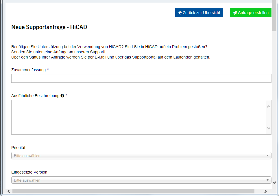
The new ISD support portal will be available for customers in Germany from 1 October 2019. For customers in other countries, the launch is scheduled for January 2020.
Accelerated graphic preview
From HiCAD 2019 SP1, the graphic preview in the ICN is always drawn via OpenGL. The OpenGL mode is used, which most closely corresponds to the current view mode. This leads to a significant acceleration of the preview.
So far, the amount of possible layers could be set via configuration management System settings > 2-D lines with the parameter Maximum number of layers. From Service Pack 1 onwards, this setting is not available. The amount of possible layers has been set to 1000 (layer 0 to 999).
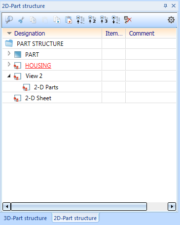
Like the 3D-Part structure tab in the ICN, the 2D-Part structure tab has had a redesign:
In connection with the new representation of the 2-D Part structure, system files have been renamed as follows:
|
Up to HiCAD 2019 |
As of HiCAD 2019 SP1 |
|---|---|
|
BRW_2DTEILATT.HDB |
ICN2D_MULTIATTRVIEW.HDB |
|
BRW_2DDBATTR.hdb |
ICN2D_MULTIATTRVIEW_DB.HDB |
If available, cloud directories such as Microsoft OneDrive or Dropbox are displayed when loading or saving drawings via HiCAD Explorer. These can be found in your user folder.
In HiCAD Info window, numbers of installed Hotfixes are being displayed in addition to the current HiCAD version number (including build number). To show the Info window, open Help Topics and Information and select HiCAD.
Views of developments of Sheet Metal can be created shortened as from now. The Settings for views window has been enhanced accordingly.
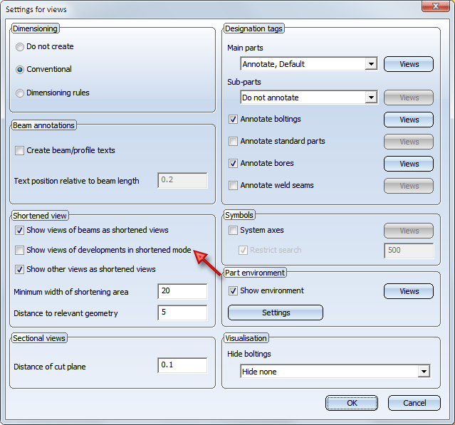
The pre-settings can be defined for each intended purpose under ..> Automatic drawing derivation > Production drawing > Usage-dependent > NAME > Views > Shortened view, with the name being the name for the respective intended purpose.
So far, only the position of Steel Engineering plates and beams has been dimensioned (as sub-parts). In practice, simple Sheet Metal plates consisting of one flange are in use instead of Steel Engineering plates. As of HiCAD 2019 SP1 also Sheet Metal plates are dimensioned automatically as attached parts of a welded assembly.
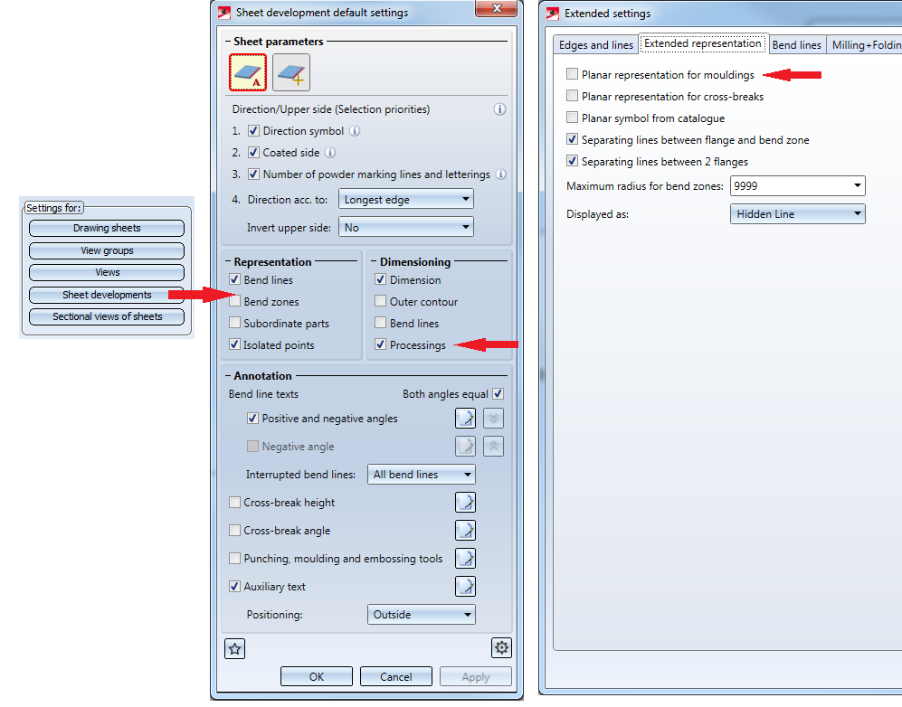
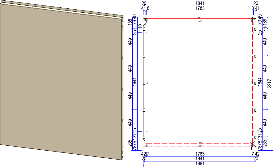
If the construction contains sheets with agrafes, e.g. suspended ALUCOBOND® tray panels, the position of the agrafes in derived drawings is only dimensioned if the checkbox Processings is active in the settings for sheet development. However, agrafes are only dimensioned if the checkbox Planar representation for mouldingsis NOT selected under Extended settings > Extended representation.
Start and end point of the agrafe are taken into consideration in dimensioning the outer contour.
The dialogue window Load usage-dependent configuration has been revised.
The middle column shows the usage type from which the configuration template is used.

The selection can be filtered using the search field at the top right of the dialogue window. Filtering can be cancelled by clicking on the delete icon.
The change affects the functions:
 Rules for automatic dimensioning in derived drawings for dimension type "dimensioning rules"
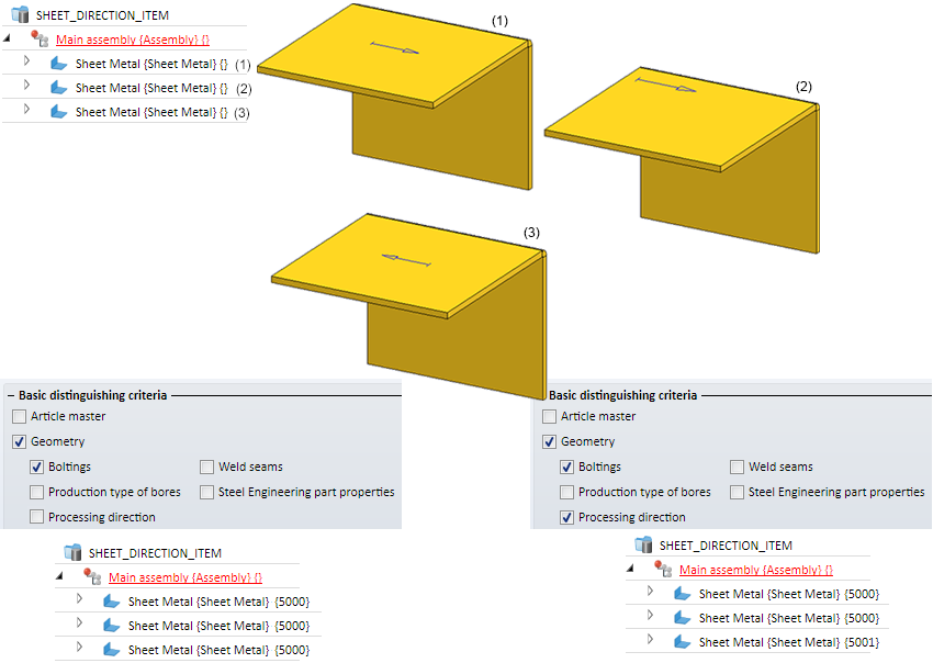
For the Itemisation a further distinctive criterion, the Processing Direction, can be chosen for Identical Part Search.
An example:
The image depicts three geometrically alike sheets with Processing Direction. For Sheet 1 and Sheet 3 Direction symbol one-sided 40 mm was chosen, for Sheet 2 Direction symbol two-sided 50 mm was chosen. If the checkbox Processing Direction is unticked during Itemisation, all Sheets are assigned to the same Item number. If the checkbox is ticked (despite different position of symbols on the flange), only Sheet 1 and 2 are assigned to the same Item number. Sheet 3 is assigned to a different Item number because the Processing Direction is opposing.
Previously, when the BOM relevance of a part was removed, the corresponding item data (item number, item text, and so on) was deleted. The item number of the part was then set to 0. As of HiCAD 2019 SP1, this behavior has been changed. If the BOM relevance of a part is removed, the item number is not removed, but only marked as invalid. However, the other item data, such as the item text, is not retained. Invalid item numbers are represented crossed out in the ICN.
If the BOM relevance is assigned to the part again later, the "old" item number is restored during automatic Itemisation, provided that the checkbox Preserve existing numbers where possible is active in the Itemisation settings. However, the current settings are used for the item text and not those that were active when the BOM relevance was canceled.
Use case:
In practice, it sometimes happens that parts lists are only created for a certain quantity of parts. To do this, you can remove the BOM relevance of the unwanted parts, create the BOM and then reassign the BOM relevance. Then start the automatic positioning again (with active checkbox Preserve existing numbers where possible).
Example:
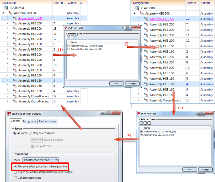
(1) Original model drawing, (2) Remove the BOM relevance for the parts with item numbers 13 and 3. The item numbers 13 and 3 are therefore invalid. (3) BOM relevance is set again. (4) The new positioning restores the invalid position numbers.
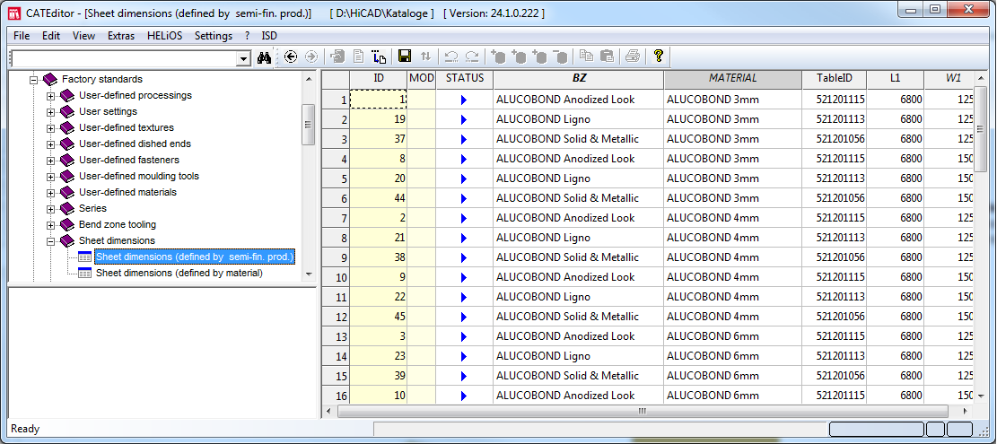
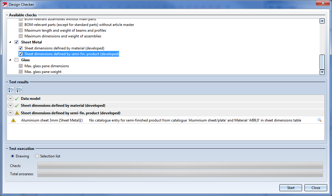
An additional check is available for Sheet Metal in the Design Checker. The new check Sheet dimensions defined by semi-fin. prod. (developed) checks the dimensioning for semi-finished products. For this, the table Sheet dimensions (defined by semi-fin. prod.) under Factory Standards> Sheet dimensions is evaluated in the CATeditor. The table shows the maximum length and width of the semi-finished product as a function of the TableID of the semi-finished product. The dimensions of the ALUCOBOND panels stored in this table are predefined by ISD. However, you can extend this table as required for other semi-finished products.
In previous versions, the selecting of parts in rectangle has behaved differently in shaded and non-shaded views as well as in referenced and "regular" parts. As of HiCAD 2019 SP1, the conduct is standardised as follows:
To select all parts/assemblies within a rectangle for processing, draw a rectangle by simultaneously pressing the left mouse button and the CTRL button. With regard to assemblies, the following should be observed:
The behavior is independent of the representation mode.
A special treatment applies to sheets. If all flanges and bending zones of a sheet are in rectangle, the corresponding superordinate part is also selected.
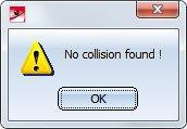
The collision check functions now also display a message if no collision was found:
With the function Article master sync when saving  you can specify which HiCAD part attributes are to be assigned to HELiOS article master when saving. These attributes are then compared each time they are saved. As of SP1, this function is no longer available in the menu function under Drawing > Itemisation/Detailing < Attr.... Instead, the function is now available via the menu function HELIOS PDM under Others > Link....
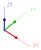
For functions that refer to axes, planes or the origin of the active coordinate system, it was previously always possible to select them via the context menu. Since HiCAD 2019 SP1, additional symbols are now displayed in the drawing, which can be clicked directly for selection.
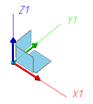
Only the symbols that can be used are displayed; if, for instance, a direction is queried, only the coordinate axes and the origin (as start point of a direction) are available for selection:
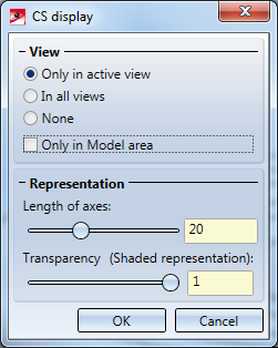
You can specify the transparency with the option Transparency (Shaded representation) under Drawing > Others > Extras > Settings, permanent > CS display .
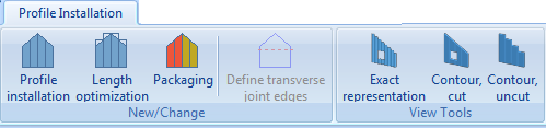
The new module Profile Installation (optional) provides convenient options to place installation elements on walls and roof surfaces within a short time.
You can find the functions on the Ribbon Profile Installation.
As of HiCAD 2019 it is automatically determined which mode is being used for Itemisation, i.e. it is not possible to select the mode via Configuration Management.
It depends on the current drawing which mode is active:
Please note that the mode Itemisation up to HiCAD 2017 will not be available anymore by HiCAD 2020.
For converting Itemisations to the Standard Itemisation as of HiCAD 2018, the function Convert to standard itemisation  is available.
As of HiCAD 2019 Textures are not any more assigned via the docking window Visual Effects. The following function is available instead (see also HiCAD 3D - What's New?)
|
|
Texture - New (3-D Part list) |
via 3-D Standard > Tools > Attr... or in the context menu of a part list via Properties |
|
|
Texture - New (3-D Part)
|
via context menu for 3-D parts under Properties |
|
|
Change texture, active part (3-D Part)
|
via context menu for 3-D parts |
|
|
New texture
|
via Drawing > Others > Extras |
In addition, HiCAD 2019 offers a multitude of textures. These are available in HiCAD Catalogue under Textures and Colours > Textures.
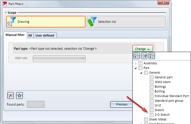
Planar sketches and 3-D sketches are different part types as of HiCAD 2019. Thus, Planar sketches  and 3-D sketches
  can be marked differently and the Part filters for the Toolbar can be set detachedly for Planar sketches and 3-D sketches.
The Novice configuration settings have been revised:
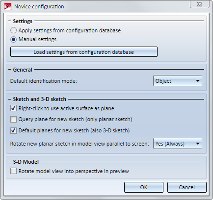
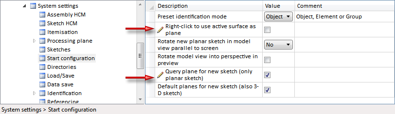
The setting (Yes) affects planar sketches only if the checkbox Query plane for new sketch is ticked.
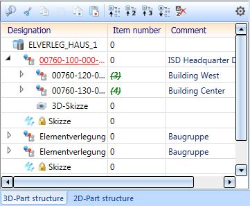
The Part structure representation in the ICN has been redesigned:
In context with the new representation of the 3-D Part structure, the following system files have been renamed:
|
Up to HiCAD 2018 |
As of HiCAD 2019 |
|---|---|
|
BRW_3DTEILATT.HDB |
ICN3D_MULTIATTRVIEW.HDB |
|
BRW_3DDBATTR.hdb |
ICN3D_MULTIATTRVIEW_DB.HDB |
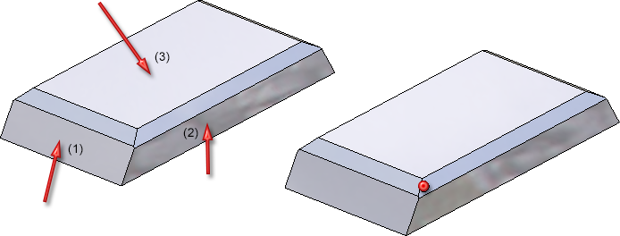
With the new function Intersection of three planes  it is possible to determine an intersection - even in theory - of three planes. This is often used for Element Installation to specify the origin of the Fitting CS in order to determine the exact fitting direction.
Example:
Here, the intersection of plane (1), (2), and (3) have been identified by selecting the respective area.
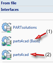
As of HiCAD 2019 you are granted with free access to more than 500 manufacturer's catalogues via the web catalogue parts4cad by Cadenas. The access to the extended catalogue range (DIN/ISO/EN… Norms + all 800 manufacturer's catalogues) is fee-based.
The following term has been standardized as of version 2019:
|
Previously |
As of HiCAD 2019 |
|---|---|
|
Figur |
2-D Part |
Furthermore, it is displayed whether a read-only file has been opened in the title block.

A file is considered as read-only file, if
For selecting a superordinate part in a drawing, click on the part with the left mouse button and hold it. Click additionally on the right mouse button. HiCAD automatically selects the closest superordinate part and marks it. Clicking again on the right mouse button enables further search for parts.
So far, this function has been enabled only for general selection of parts before calling a function. As of HiCAD 2019, this is also possible when a part selection is started via a new function dialogue, for instance the definition of exploded views.
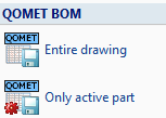
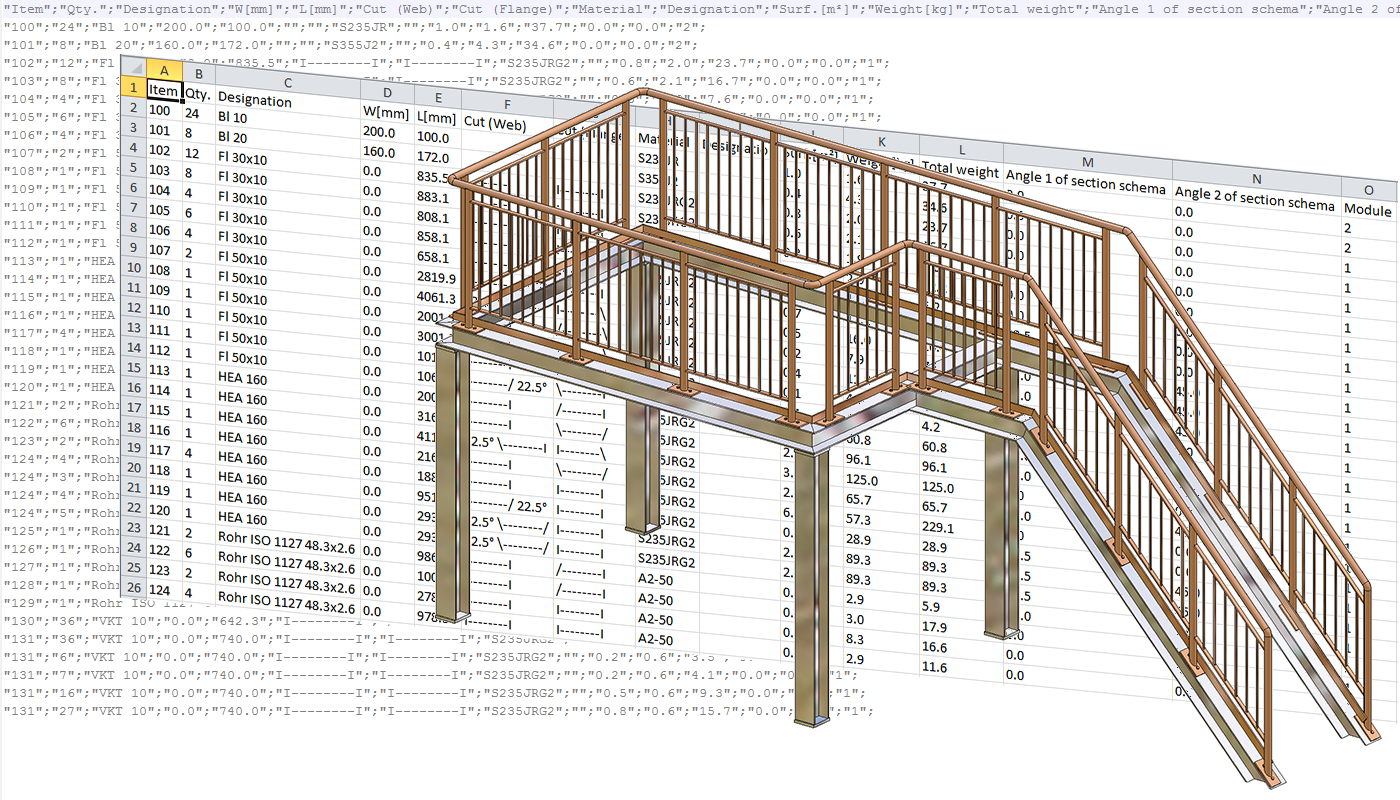
HiCAD 2019 supports the export of QOMET-specific BOMs. QOMET is an ERP system specialised in steel and metal engineering.
The BOM can either be exported for the complete drawing or active part and contains particular columns of the Excel BOM in Steel Engineering (hicad_Stahlbau.xlsc ) relevant for the QOMET system in particular. The file is exported as CSV.
The respective functions for exporting the BOM are available under Drawing > Save/Print > Save as...
As of HiCAD2019 continous sectional views are only created if the bending zone is parallel or perpendicular to the view CS.
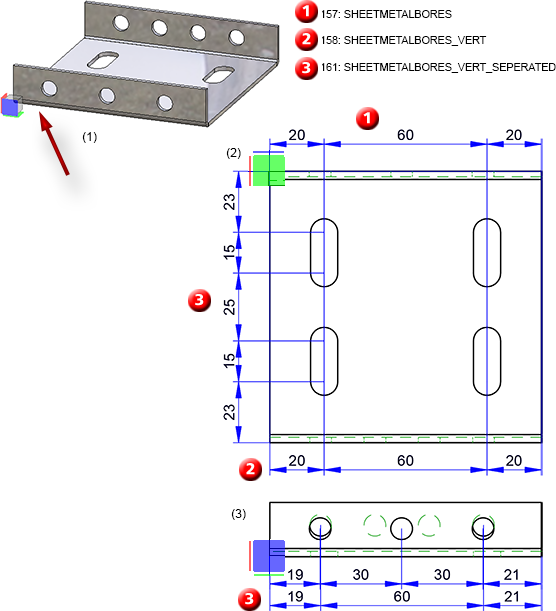
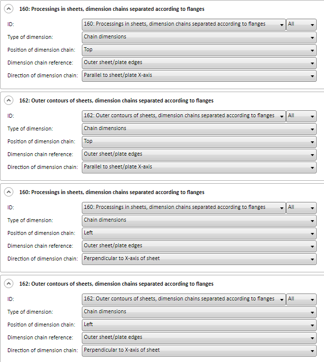
In facade engineering, sheet metal is used as bent profile or tray panel. It is often requested that these sheet metals are also to be dimensioned automatically in standard views when creating workshop drawings (top view, side view, front view) and that the processings are taken into consideration next to the outer dimensions.
|
157 |
SHEETMETALBORES |
Processings in sheets |
|
158 |
SHEETMETALBORES_VERT |
Processings in sheets incl. processings perpendicular to view |
|
159 |
SHEETMETALOUTLINE |
Outer contours of sheets |
|
160 |
SHEETMETALBORES_SEPERATED |
Processings in sheets, dimension chains separated according to flanges |
|
161 |
SHEETMETALBORES_VERT_SEPERATED |
Processings in sheets incl. processings perpendicular to view, dimension chains separated according to flanges |
|
162 |
SHEETMETALOUTLINE_SEPERATED |
Outer contours of sheets, dimension chains seperated according to flanges |
The sheet metal is treated as superordinate part including its flanges and bending zones. The prerequisite for these dimensioning rules is that an appropriate coordinate system has been defined with the functions via Alignment of derived drawingsin the context menu for 3-D parts.
Example:
The following picture shows a sheet metal with different bores. For the alignment of derived drawings the top view has been placed in the flange surface (1). (2) shows the front view of the drawing derivation and (3) the top view. The configuration DEFAULT (SHEETMETAL) has been used as template - enhanced by rule 157, 158 und 161.
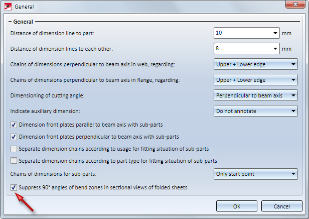
As of HiCD 2018 it was possible to determine whether the 90° bend angle should be dimensioned for drawing derivation in the sectional view of folded sheets. In order to disable the dimensioning of 90° bend angles the system data STAB3DPAR.DAT (for new customers) and STW_DIMSETTINGS.XML had to be adjusted manually so far.
As of HiCAD 2019 this function can be set via Dimensioning Settings . The dialogue window General has been enhanced with the checkbox Supress 90° angles of bend zones in sectional views of folded sheets.
As of HiCAD 2019, shortenings are displayed simplified.
The following depiction shows the difference:
The dialogue window for usage-dependent configurations has been rearranged more clearly. This concerns the following functions in particular:
The first column shows the configuration. The second column shows the usage for the configuration.
Via the function Help > Customer feedback now also the Data protection notice: Collection of data for constant GUI optimisation can be opened.
The same applies to the HiCAD installation for the setup step GUI optimisation .
So far, this system file has contained settings for working with a tablet as input device as well as regulation for time interval for double-click. This file will be cancelled as of HiCAD 2019 because tablets are not being supported as input device. The parameter Time interval for double-click can be defined via System settings > Identification in the configuration management.
With the new function Article master sync when saving you can specify which part attributes are to be synchronized with which article master data. These attributes are synchronized automatically with each saving procedure.
Please note that the Transfer part attributes to HELiOS checkbox must be activated the ISD Configuration Management via System settings > HELiOS.
You find the function via Drawing > Itemisation/Detailing > Attr...
WIth the new tab Server Monitor you can look at available and occupied modules. By means of the listed licenses you can easily find out which colleague blocks licenses and e.g. contact them in case if you need a license.

HiCAD Basics - Overview of Topics
|
© Copyright 1994-2019, ISD Software und Systeme GmbH |


