
Project: HiCAD Parametrics
In previous versions, isolated points in assemblies were interpreted as movable points, so the HCM attempted to move the HCM assembly containing the HCM model as soon as such points occurred in constraints. This behaviour has now been changed.
The geometry of parts, in particular isolated points of assemblies, will be interpreted as "fixed" by a HCM model existing in a contained part. Constraints between these geometries and the part coordinate system of the contained part can no longer be set. Already existing constraints will, of course, be preserved.
However, constraints between the geometry and its sub-parts can still be set, which allows you to determine the position of the sub-parts.
In the Sketch HCM the constraints will now take into account whether the use of external references has been activated or deactivated. An external reference exists if a HCM constraint refers to a part that does not belong to this sketch.
In existing sketches the use of external references is active by default, in order to keep the existing behaviour of these sketches. Created new sketches behave according top the settings specified in the Configuration Editor: The value chosen at System settings > Sketch HCM > Use external references determines your default value. After new installations, external references are not used by default.
If you right-click on the empty area of the HCM window of the ICN, a context menu with the options External reference: Use or ... do not use, respectively, will be displayed, which shows you the current setting for external references. After choosing this option, a dialogue window will be displayed, allowing you to choose between the settings Use and Do not use.
When defining new positional or dimensional constraints in sketches or 3-D sketches, the point option (M) Mid-point of edge will now no longer be suggested by the Autopilot, as this point option is only rarely used in practice.
However, it is still possible to select this point option manually.
The HCM window for the display of constraints in sketches and 3-D assemblies in the ICN has had a redesign, now featuring a new, modern Look & Feel and a multi-column display.
Also, you can now use filters such as Deactivated constraints or Constraints with external references, or the new function Zoom to constraint.
In older versions, HCM dimensions in sketches were placed with regard to their first base point. In case of geometry changes, the new dimension was placed in such a way that the length of the projection line of the first base point was identical to the length before the change, which frequently lead to unsatisfactory results. From SP2 onwards, the placement logic is different. The length of the shortest projection line after the change is now identical to the length of the shortest projection line before the change. In the process, cases may occur where the shortest projection line could be applied to different base points.
Example:
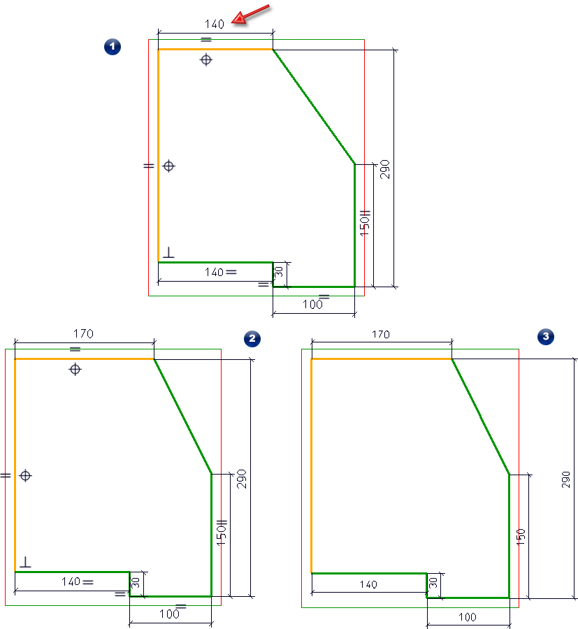
In the original sketch (1) the marked HCM dimension is changed from 140 to 170. (2) shows the result in HiCAD 2019 SP2, (3) shows the result in HiCAD 2018.
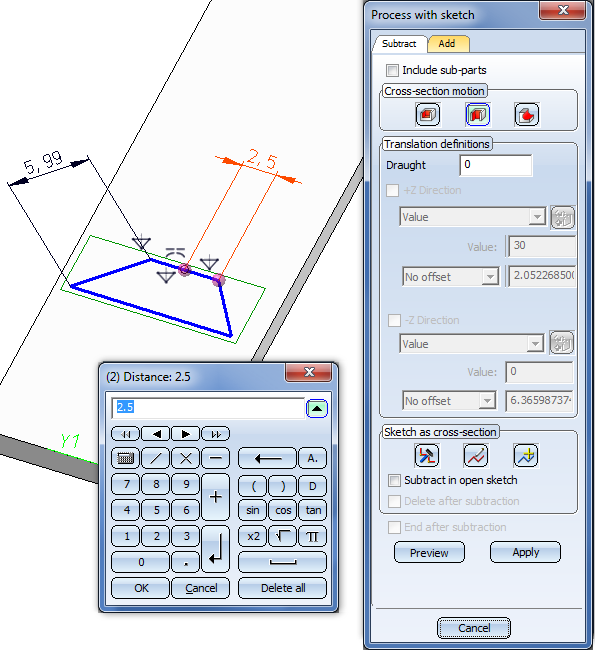
Youcan now change HCM constraints directly in the model drawing even while a dialogue window is open. This concerns, for example, the dialogues of the functions Extruded solid, Revolved solid, C-edge sweep, Subtract or Add.
If the HCM setting Enter constraints is active, positional constraints will be automatically set when creating isolated points in planar sketches or 3-D sketches. These depend on the chosen point option:
When creating a constraint that has not yet been fulfilled at the time of its creation, graphical elements or parts need to be transformed.
A good example for this would be a Parallel constraint between 2 non-parallel edges. In previous versions, one could not tell which of the two affected parts needs to be rotated in order to fulfil the constraint (except for cases where one of the parts has been determined by further constraints).
This behaviour has now been changed in such a way that the first selected element will not be transformed if possible.
For Symmetry constraints, HiCAD will attempt to preserve first the symmetry axis, and then the first selected element.
For Mid-point constraints, the order of the queried elements has been changed: First, two elements, and then the mid-point will be requested. Accordingly, the mid-point instead of the selected elements.
When you select a HCM constraint in the ICN, the sketch elements affected by it will be highlighted in your drawing. If the display of constraints has been deactivated, the concerning constraint will be displayed. If the constraint refers to an axis, plane or the origin of a coordinate system, these will also be displayed.
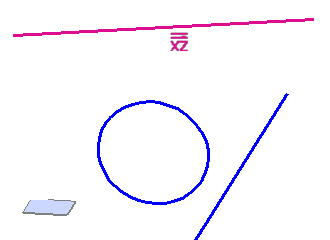
Example: The constraint "Parallel" between the line and the XZ-plane has been selected.
The highlighting will remain until you choose a different constraint or a different part.
When the display of positional constraints for sketches has been activated, the symbol for parallelism of circles and ellipses placed parallel to a plane is no longer shown in the centre, but next to the circle/ellipse. This concerns both full circles/ellipses and arcs.
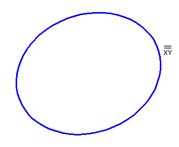
Excluded here are ellipses in planar sketches, if the parallelism refers to the main axis. Here, the symbol for the positional constraint will still be shown at the centre of the ellipse.
The editing of HCM constraints in sketches of a Feature step is now also possible if the editing of the sketch has been started by choosing Edit sketch for a Feature in the Feature log.
In previous versions this was only possible if the editing of the sketch was started by the opening of the dialogue window of the feature, and choosing Sketch > Process sketch.
In previous versions it could happen in certain constellations that the HCM model reacted in an unexpected manner when perfoming mirrorings on one of its parts.
This behaviour has now be corrected, so that this problem no longer occurs.
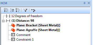
If you use HCM constraints in conjunction with Sheet Metal parts, references will often refer to flanges or bend zones. In older versions, the reference was often displayed as "Sheet flange" or "Bend zone" in the HCM window of the ICN.
Now, such reference are always displayed as "Sheet Metal", i.e. the entire sheet:
Selected HCM dimensional constraints are now highlighted in the drawing by the special colour Marking 5 (default: Orange).
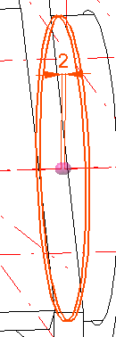
You can change this colour via the Colour Editor if desired.
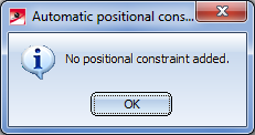
If the functions Automatic positional constraint or Automatic dimensional constraint have not created any constraints, an appropriate message will be displayed:
While the display of degrees of freedom in sketches is active, rotatory degrees of freedom will now always be shown on the mid point straight lines, circular arcs or elliptic arcs.
Through various optimizations the performance of HiCAD with regard to the loading of model drawings containing very many HCM constraints could be increased significantly.
The Automatic positional constraints  function for planar sketches and 3-D sketches now contains, beneath the Parallel option, the additional Also on Parts CS option.
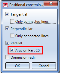
If this option has been activated, line elements running parallel to an axis (or, in 3-D sketches, also parallel to a plane) of the Part CS, will be assigned a Parallel constraint with regard to it. If you deactivate this option, HiCAD will show the same behaviour as previous versions, i.e. no parallelisms with regard to axes or planes of the Part CS will be considered, just parallelisms of lines.
The positional constraints for planar sketches and 3-D sketches were expanded by the new constraints Align to CS axis  . This constraint replaces the previous constraints Align to X-/Y-/Z-axis.
If you apply this positional constraint to a straight line of a sketch, HiCAD determines to which CS-axis the straight line has the smallest angle. A Parallel constraint will then be applied to this axis.
For planar sketches you can also apply this constraints to 2 points. In this case the angle between a virtual straight line running through these 2 points and the CS axes will be considered. An Equal distance constraint with regard to this CS axis will then be applied for the 2 points.
When changing dimensions, this could result in an unwanted switching of the chirality in previous HiCAD versions. In other words: While the positional and dimensional constraints were preserved, the direction of measurement could change unexpectedly.
This effect can be demonstrated by way of a very simple example of the two panels shown below:
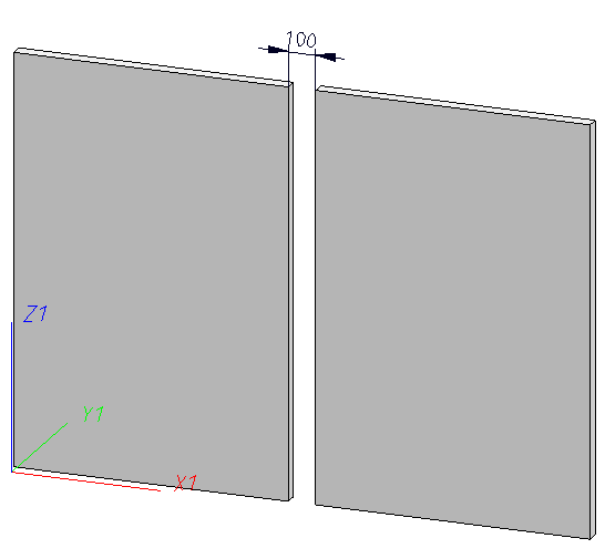
The left panel has been fixed. Both panels are kept on one plane by means of Coincidence constraints, and a Distance constraint defines a fixed distance between the edges on the borders of the 2 panels.
If you increased the width of the left panel by 200 mm in older HiCAD versions, the result looked as follows:
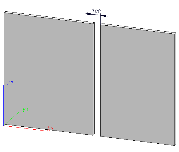
Formally speaking, this is still "correct" - the two edges still have a distance of 100 mm. However, this isn't usually the intended result.
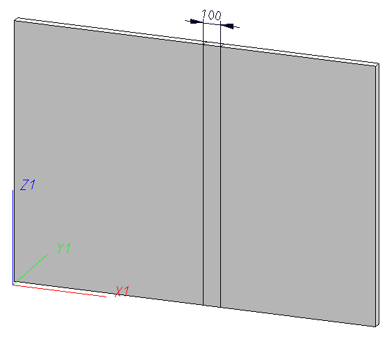
From HiCAD 2401 onwards, it will be attempted to preserve the chirality after applying changes to the HCM system - here, the intended result looks as follows:
Positional constraints containing a reference to an axis or plane of the coordinate system will now be given particular attention: For instance, a parallelism constraint referring to the X-axis of the Sketch CS will not just be listed as Parallel in the ICN, but as Parallel to X.
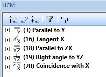
Also, the symbols of the positional constraints will be displayed both in the ICN and (if the display of positional constraints in sketches has been activated) and in the sketch:
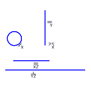
In this sketch you can see immediately that in this 3-D sketch the circle, for instance, has been fixed to the X-axis via a tangential constraint, and the lower line runs perpendicular to the YZ-plane.
If the Enter constraints setting has been activated in the Sketch HCM, no distinguishing was made between "normal" constraints and constraints with external references in previous versions. To avoid errors in the design it may help in some cases not to work with constraints with external references. In this case the automatic assigning of constraints during drawing of sketches could not be used.
HiCAD 2019 offers the new option Use external references:
If this checkbox is deactivated, constraints that would contain external references will no longer be automatically created. This option is deactivated by default, which would be identical to the behaviour of HiCAD before Version 2019.
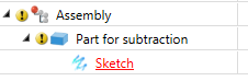
References to immediately superordinate parts or assemblies are not regarded as external references and will therefore be created even if the Use external references checkbox has been deactivated. An example of this is a sketch for a subtraction: If this sketch is located immediately beneath the part to which the subtraction is to be applied, it can still automatically obtain distance constraints to the edge of the part, e.g. when using the Offset function.
When assigning constraints to a 3-D sketch, the Sketch HCM has always referred to the Part CS of the 3-D sketch. However, the active coordinate system was still displayed in the process, which could be rather confusing.
This has been changed now, so that the Part CS will automatically be displayed on a 3-D sketch when you choose a function that normally uses this type of coordinate system. After applying the changes, the display will switch back to the previously used coordinate system.
The behaviour of the Part HCM and the constraints has not changed; this change refers only to the display of the coordinate system during assigning of constraints.
In previous versions the configurations available via the ParConfigComp.exe tool contained different configurations for the display HCM constraints and symbols. These inconsistencies have now been removed, so that the same settings are now used in every configuration:
You have now the option to automatically update HCM models of superordinate assemblies when you apply changes to a part. This function can be activated or deactivated in the 3-D Part HCM Settings dialogue window.
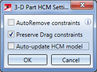
After new installations this function is activated by default; after update installations, in contrast, it will be deactivated in order to keep the behaviour known from previous versions.
When using the UNDO function on sketches, HiCAD no longer distinguishes between sketches with and without HCM constraints, i.e. a step-by-step UNDO is now also possible for sketches with automatic HCM constraints. The number of UNDO steps is unlimited.
This applies to both planar sketches and 3-D sketches.
The 3-D Part HCM and the Sketch HCM now offer the new Toggle visibility of degrees of freedom 
 function. This function allows you to switch the display of the degrees of freedom in the current HCM system in a drawing on or off.
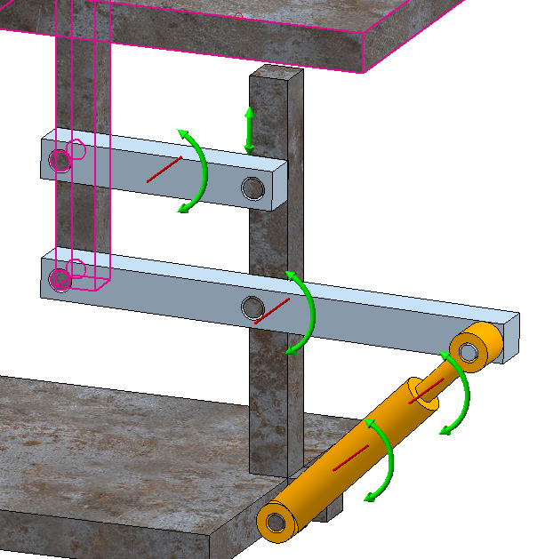
If the display has been activated, arrows indicate how many and which axes are still available for possible movements and rotations.
Extensive descriptions of these functions and the meaning of the displayed arrows can be found in the relevant Help chapters for the Sketch HCM and the 3-D Part HCM.
The HCM window in the ICN has been revised with particular focus on more user-friendliness. The changes include:
The changes for sketches are described here.
The positional constraint  Equal distance can now be applied not only to planar sketches, but to 3-D sketches as well.
The Equal distance constraint is now also available in the 3-D Part HCM.
The structure of the Ribbon tabs has been optimized, so that the most frequently needed HCM functions are now directly available and need no longer be called from sub-menus.
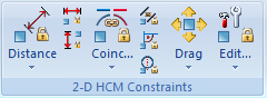
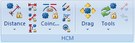
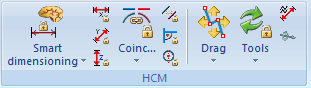
You have now direct access to functions for dimensional constraints in X-, Y- and Z-direction (with the latter, of course, being not available for 2-D parts), as well as to Coincidence, Parallelism, Right angle and Fixing constraints.
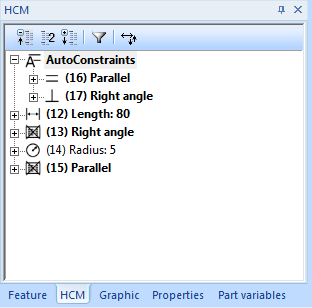
Positional constraints that have been created via the Automatic positional constraints function can now be found beneath an item called AutoConstraints. If desired, you can move these constraints out of this item via Drag & Drop , or choose the context menu function Remove from AutoConstraints to move the constraint out of the AutoConstraints item and list it among the "normal" constraints instead.
The positional constraints for free-form curves, i.e. Equal parameters, Equal direction, Equal 1st/2nd derivation and Equal bend have been removed.
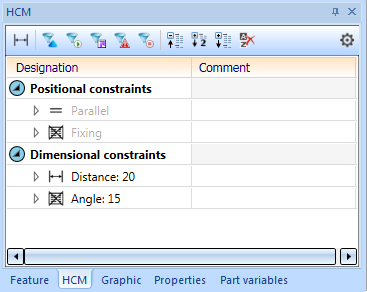
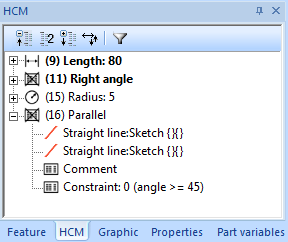
You have now the option to specify Comments for HCM constraints in composite edges and in 3-D assemblies. These have no influence on the model; their purpose is to describe the meaning of individual or all constraints, especially in larger model drawings.
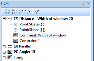
On the HCM tab of the ICN, expand the individual constraints and double-click the Comment entry. You can then specify a text for the Comment, which will then also be displayed after the designation of the constraint.
To delete a comment text again, double-click the Comment again and remove the text in the dialogue window and confirm with OK.

|
© Copyright 1994-2019, ISD Software und Systeme GmbH |