
Project: Configuration Management
The settings from the system files ABWPAR.DAT and ABWCOL.DAT have been moved to the Configuration Editor.
You can now find the settings from those DAT files in the following directories:
|
Sheet Metal > Sheet development Sheet Metal > Default setting Compatibility > Sheet development up to HiCAD 2016 |
|
|
Compatibility > Sheet development up to HiCAD 2016 > Extended settings |
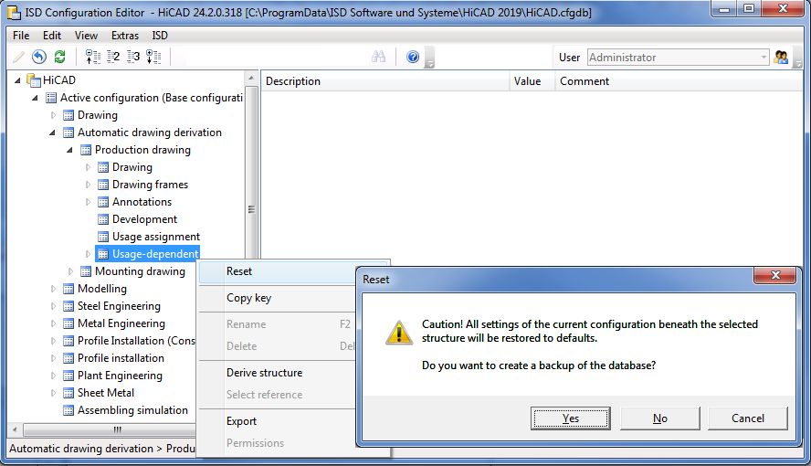
In the Configuration Editor you have now the option to reset changed values for a defined node within the tree structure in one step.
For instance, if you have modified the default settings of the dimensioning rules in various directories, you can right-click the Usage-dependent entry, choose Reset, and, after confirming the security prompt with, restore the modified settings to defaults again. If you confirm with Yes, a backup ([Installation directory] > Configuration > HiCAD.cfgdb.[Date]) will be created, in case you may require the modified settings later again. If you choose No, the values will be reset without creating a backup.
The texts for shortened views (Automatic drawing derivation > Production drawing > Usage-dependent > ... > Views > Shortened view) have been optimized, in accordance to the Settings for views dialogue window in HiCAD.
In previous versions, leader lines frequently ran straight through processings (e.g. bore patterns) when using the automatic placing of annotations for standard processings. This effect has been corrected in HiCAD 2019 SP2; now, leader lines of processings will always end at the nearest standard processing. Furthermore, leader lines can now be placed either on or outside of parts, which is possible for both production drawings and mounting drawings. This can be set in the Configuration Editor at
by setting the parameter Standard processing on part accordingly.
HiCAD supports the creation of usage-dependent workshop drawings for automatically derived production drawings. In the process, individual dimensioning rules can be determined, e.g. for columns, girders, particular profiles, railings etc. Conversely, the mounting drawing creation works independently from the usage of the parts and assemblies - what is located in the selected box will be considered. In most cases, this option is sufficient -the essential parts can be automatically annotated and grids can be automatically dimensioned.
However, to be able to create overall drawings with an automatic generation of relevant dimensions for sub-structures of element installations for facades, too, sets of dimensioning rules can be specified in the Configuration Editor at Automatic drawing derivation >Mounting drawing > Annotations > ..., although in a limited way. Via these sets of dimensioning rules you can define what is to be dimensioned in which way (dimension type, position, reference etc.) and in which view.
As with detail drawings, you can now also transfer article attributes of individual parts to document attributes of drawings with multiple parts. For this purpose the new parameter Article attributes for drawings with multiple parts has been added at PDM > Management+BIM > Production drawings.
When saving drawings that were created via Management+BIM, you have the option to execute an individual script for automatic reworking. For this purpose the new parameter Rework of drawing has been added at PDM > Management+BIM > Production drawings.
There you can choose between detail drawings, drawings containing multiple parts, mounting drawings and customer drawings. Mark the corresponding entry in the listbox to determine for which drawing types a rework via script is to be carried out.
In previous versions the item texts were updated after each change to the model drawing. In large drawings this can lead to a drop in performance, in particular if attributes from superordinate assemblies are used in the item texts. Therefore, SP2 offers the new parameter Update item text at System settings > Itemisation, which allows you to determine when item texts are to be updated.
The HiCAD Parameter configuration for Steel/Metal Engineering has been changed, with the aim to provide a clearer overview of Steel Engineering workshop drawings.
Two new parameters for section schemas are available in the Configuration Editor at Steel Engineering:
Cutting angle reference in section schema
Here you can set to which leg the angles specified in the section schema refer.
Do not show cutting angle in section schema if cut surface:
Use this parameter to define the conditions under which no cutting angle is to be output in the section schema because the total length does not correspond to the trimmed length.
The settings for Sheets with identical cross-sections are now available as a sub-entry of Sheet Metal.
The "Bend zone limit for warning" entry for connecting sheets has been removed.
You have now the option to define layer-specific printing settings in the P+ID module via the Configuration Editor (at Plant Engineering > P+ID). For this purpose you can define a list with layers that are to be excluded for printouts.
The entries for Material selection at Steel Engineering > Default material > Table ID for default material and Item ID for default material have been replaced by a more convenient catalogue selection option.

The settings for the sorting of the ICN entries are no longer relevant for the new 2-D and 3-D ICN. The corresponding setting options have therefore be removed from the Configuration Editor.
All entries can now be directly sorted in the new ICN.
In previous versions the possible maximum number of layers in HiCAD could be set in the Configuration Editor at System settings > 2-D Lines with the parameter Maximum number of layers. From Service Pack 1 onwards, this parameter will no longer be available. The number of possible layers has now been set to constantly 1000. (Layer 0 - 999).
In the Configuration Editor you can now also specify whether upper and lower case letters are to be taken into account when translating texts. The default setting is Consider.
You can find this option at System settings > Miscellaneous > Translation -Upper and lower case letters. For a change of this setting to take effect, HiCAD needs to be restarted.
The setting will not be saved in the drawing or in the text; it is a pure system setting.
Exploded layouts, too, can now be considered for export as
files. The Configuration Editor and the export dialogue have been expanded accordingly for this purpose. In the Configuration Editor at Interfaces the Consider exploded layouts checkbox is available for the above formats.
In several Plant Engineering functions a marking arrow pointing on the currently processed edge or part will be displayed. The size of that arrow can be set in the Configuration Editor at Plant Engineering > Layout plan. The value must be between 10 and 300 pixels; the default value is 80.
The settings from the TABPAR.DAT file for a working with a tablet computer as input device and the specification of the time interval for double-clicks have been moved to the Configuration Editor (ISDConfigEditor.exe). The file has been withdrawn with the release of HiCAD 2019, since tablet computers as input devices are no longer supported. The Time interval for double click parameter can now be specified in the Configuration Editor, namely, at System settings > Identification.
HiCAD 2019 automatically determines the itemisation mode to be used. That is, it is no longer possible to choose the mode via the Configuration Editor.
In previous versions, existing article masters of semi-finished products were not transferred to HiCAD when inserting attached parts such as Steel Engineering connections, stairs, railings, element installations, profile installations etc.
From HiCAD 2019 onwards this behaviour can be changed via a setting in the Configuration Editor: At PDM > HiCAD-HELiOS Interface you can find the parameter Add semi-finished product article when loading. The ISD default setting is No, i.e. the article master of semi-finished products will not be transferred.
You can now determine in the Configuration Editor whether
are to be automatically transferred to HELiOS upon each saving in HiCAD.
The relevant setting can be found at System settings > HELiOS > Transfer part attributes to HELiOS.
If you have chosen a standard template (Mechanical Engineering, Steel/Metal Engineering or Plant Engineering) and activated the Novice configuration in the Extended settings of the HiCAD installation, or via the Parameter configuration (ParKonfigComp.exe / ParKonfigUser.exe), this will also influence the settings in the Configuration Editor!
For automatic part annotations you can now use part filters, to which certain annotation templates can be assigned in the Configuration Editor. In the paragraph Using part filters for automatic part annotation it is explained how to use these filters.
The assigning takes place via the Configuration Editor at Drawing > Annotations > Automatic annotation > Filter-Annotation template assignment.
For heights above datums, additional symbols for dimension line terminations are available:
 Height above datum, circle, with cross, unfilled and
 Height above datum, circle, with cross, half filled.
For this purpose the dimension parameters and the settings in the Configuration Editor at Drawing > Dimensioning, 3-D... have been expanded accordingly.
AS of HiCAD 2019 new options for the 2nd dimension figure will be available. Also, the setting options for 3-D dimensions at Drawing > Annotations > Dimensioning, 3-D have been expanded accordingly.
When working in read-only model drawings you have the option to lock referenced parts of the drawing against processing by other users. For this purpose the parameter Lock referenced parts if model drawing is read-only is available at System settings > Referencing. The default setting is No.
The following new parameters are available at PDM > Management+BIM:
The Profile installation module is configured via the following settings in the Configuration Editor:

Configuration Management (CM) • User Interface (CM)
|
© Copyright 1994-2019, ISD Software und Systeme GmbH |