Settings > Docking window function.
 Project: HiCAD Basics
So-called "docking windows" that are windows contain functions and settings for specific construction aids or tasks. These windows are attached to the edges of the screen and can be expanded can be shown and hidden.
HiCAD offers the following docking windows:
|
Window |
Contents / Purpose |
Position on screen |
|---|---|---|
|
Faster opening of HiCAD drawings (.SZA) |
Right
|
|
|
Insertion of joints and connections, fasteners, stairs and railings or other objects |
Right |
|
|
Assigning of panoramas for simulation of environments |
Right |
|
|
Integration of freely definable plugins |
Right |
|
|
Tool allowing simulations of movements of parts |
Bottom |
|
|
Displays the part variables of the active part |
Left |
|
|
Shows a log of an exploded view of a model drawing |
Right |
The following options are available for the processing of the windows:
You can change the size of the individual drawing windows by dragging the window frames to the required size (press and hold down LMB and drag).
The windows as well as individual tabs of the ICN can be hidden and redisplayed. For this you use the Settings > Docking window function.
A context menu provides further processing options for the windows. You activate the context menu by right-clicking on the required window.
 symbol at the top right of the window. The symbol changes its appearance to
  .
.
Settings > Docking window function. Undocked windows can be freely moved with the mouse. Place the cursor on the caption bar of the window, press and hold down the LMB, drag the window to the required position and drop it by releasing the LMB.


In addition, you can define the window as a tab of the docking window: Use the  symbol for this. If you want to revoke this assignment as tab, left-click on the corresponding tab and, while holding down the LMB, drag it to the required position.

The Drawings docking window enables a quicker opening of HiCAD drawings. (.SZA). Simply select the required folder and double-click on the required file name.
If the window is not displayed, activate it via Settings > Docking windows.
This docking window can also be switched off permanently via the Window Registry. To do this, create in the Windows Registry at
HKEY_LOCAL_MACHINE\SOFTWARE\ISD Software und Systeme\HiCAD\3
a new DWORD value (32) Bit and assign the value 1 to it.

The docking window can then no longer be activated in HiCAD. If you want to re-enable the activation of the window, set the value in the Registry to 0.
Use this docking window to fit joints and connections, fasteners, stairs, railings, or other objects in Steel Engineering or Metal Engineering drawings.
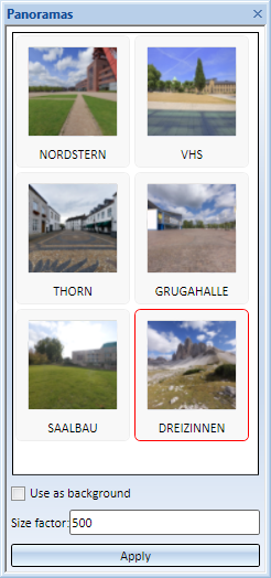
HiCAD offers the option to simulate environments. For this purpose a panorama is assigned to a Sheet or Model area. The surfaces of shaded models can then mirror this panorama, i.e. the environment.
This panorama can be used as background as well as for visualisation of environment mirroring.
Assign panorama
If the surfaces of shaded models are to mirror a panorama, i.e. the environment, activate the environment mirroring. To do this, use the Shaded view function under Shaded representation via Views > Representation > Shad... In the dialogue window, acitivate the checkbox Mirror panorama. Deactivate the checkbox to undo this effect.
HiCAD supports the integration of freely definable plugins. If such plugins have been implemented in your system, they will be displayed in a docking window. Examples are the templates for planning grids in Metal Engineering or the Sheet Metal Cost Calculation tool.
You can use this tool to simulate and animate movements of parts in an assembly. You can also use HCM constraints to link the movements of individual parts to particular conditions. To be able to define or edit simulations, the Simulation docking window needs to be open.

In this docking window the Part variable of the active part and (if any) also those of the superordinate parts are displayed.
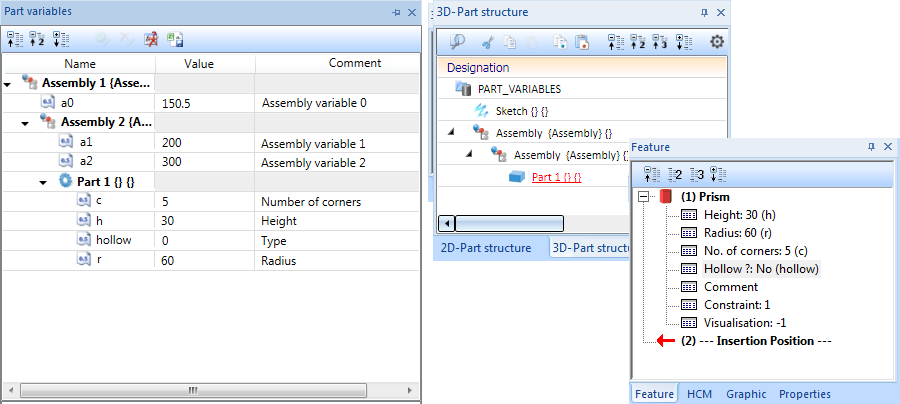
The symbols in front of the Part variables indicate the type of the variable.
Expand/collapse structure
The display of the Part variables can be expanded or collapsed by using the symbols  and
and  in the docking window above the Part structure. Use the
  icon to limit the display to the 1st and 2nd level of the part structure.
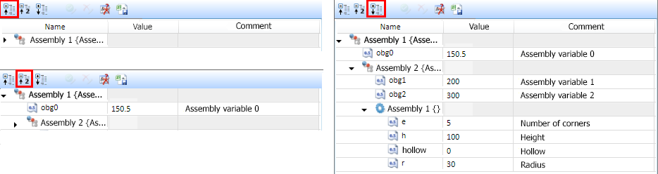
For opening/closing the variable display of each parts/assemblies use the symbols  and
and  .
.
Unused variables
With a click on the  symbol you can mark all unused variables for deletion. The deletion will only be carried out after clicking on Apply all changes
CSV export
Click  to create a CSV file that contains a list of all variables.
|
Function |
|
|---|---|
|
Add new variable |
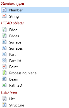
For adding a new variable, click with the right mouse button on the name of the part (or the assembly) which should be attributed to the variable. In the context menu, select the function Add new variable. In the next dialogue window, determine the name of the variable, select a variable type and set a start value. If requested, a comment can be added. The following variable types are supported:
After leaving the dialogue window, the new variable will be marked with |
|
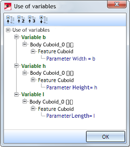
Variable, where-used |
This function shows where variables of parts/assemblies are used, e.g.
|
|
Mark unused variables for deletion |
Marks all usused variables of the part for deletion with the |
|
Mark for deletion |
Marks all variables of the part for deletion with the |
Context menu for variables and values/comments
With a click on the right-mouse button, context menus for variables as well as values/comments can be opened analogously. With these functions it is possible to
In order to change the value or comment of a variable, click on the respective field and enter the desired change. The variable will be marked with  . Only if you click Save all changes, the change will be implemented.
Save all changes
The function Save all changes in the properties docking window saves the changes of the variable list:
 will be added. will be changed.
 will be deleted.
The marks will be deleted subsequently.
By activating the function  all delete markers will be removed.
This docking window shows a log of an exploded view of a model drawing.
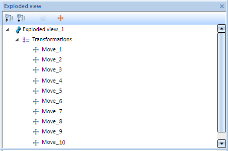
Exploded views can be edited subsequently via this log.

User Interface • Plugins • Simulate Environments • Textures
|
© Copyright 1994-2019, ISD Software und Systeme GmbH |