
The setting UNDO memory allocation for HiCAD 2-D has been removed. Since it refers only to 32 Bit versions it is no longer relevant.
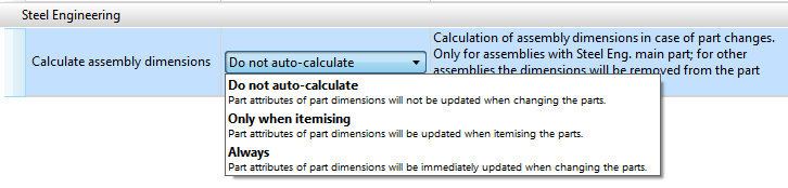
The texts at Modelling > Part Properties > Calculate assembly dimensions have been optimised and adjusted to other, similar entries in this area.
When exporting sheet developments you have the option to load the assignment of the development favourites to the part filters (Sheet Metal or Steel Engineering plates) from the Configuration Editor (at Sheet Metal > Sheet development > Filter-Development parameter assignment. Part filters are filters that have been predefined by the ISD and also the manual filters of the part search that have been stored as Favourites.
The handling of item numbers during DXF export can be specified at Sheet Metal > Sheet development >Combine item number-wise. If the checkbox  has been activated, the development of the sheets with identical item number will be exported only once. The quantity will remain unchanged.
For the DXF export of external production drawings you can now preset the Favourites of the HiCAD function Develop sheets and export as DXF in the Configuration Editor at PDM > Management+BIM > External production drawings > DXF export Favourite).
Usage assignments can now not only be defined for already existing assemblies and part types, but also for freely defined part types.
This allows you to apply your own configuration for drawing derivation to Steel Engineering series beams that have been created from 2-D cross-sections.
For example, you could define a part type called Series, and a usage assignment called Default(Series).
When you then create workshop drawings for model drawings with series beams and choose the drawing parameters From configuration, the configuration Default(Series) will be used for all series beams with the part type Series.
As of HiCAD 2018 SP2 you have the option to insert structure BOMs (besides quantity BOMs) into derived drawings. For this purpose the Settings for view groups dialogue window as well as the setting options in the Configuration Editor at Automatic drawing derivation > Production drawing > Usage-dependent > NAME > Views (NAME being the name of the respective usage) have been expanded accordingly.
The Settings for sectional views of sheets dialogue window has been revised.
The previously available setting options "Angular dimension in sections" and "Offset go-side" are no longer available here.
The representation of angular dimensions can be determined via the new dimensioning rule 156, and the distance of the go-side via the settings in the Configuration Editor at Drawing > Annotations > Coating line in sectional view.
The ISD default settings for mounting tracks can be found in the Configuration Editor at Drawing > Views > Exploded view.
Semi-finished products can be automatically transferred as sub-items of a part to HELiOS.
This can be set in the Configuration Editor at Active configuration > Base configuration > PDM > HiCAD-HELiOS interface > Product structure. Here, activate the Semi-finisherd product article as sub-item checkbox.
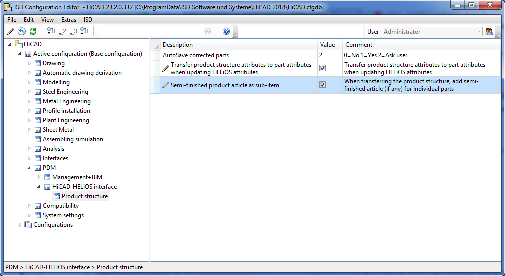
If a HiCAD model drawing (.SZA document) or an individual geometry (.KRA document) is saved in HELiOS while the option has been activated, it will be checked whether a semi-finished product needs to be saved as s structure sub-item of the corresponding part (=HELiOS article).
The relevant semi-finished product article masters will then be added as sub-item, or updated accordingly in the product structure of the part.
Dimension base points refer to geometric elements, i.e. surfaces, edges or points. If these elements are removed, the dimensions will lose their reference and will no longer be associative. In such cases the Dimension associativity - Update functions can no longer be carried out properly and the Dimension base point objects not found dialogue window will be displayed. This dialogue and the corresponding settings in the Configuration Editor at System settings > Annotations > Dimensioning, 3-D > Dialogue default setting: Handling of non-associative dimension base points have been revised in SP1.
Three new usages are available at Factory standards > Usage > Civil Engineering > Steel Engineering > Railing namely,
This allows you to assign usage-dependent configurations for drawing derivations to these railing elements, too.
In the Configuration Editor at Automatic drawing derivation > Production drawing > Usage assignment you can find the ISD default settings for usage assignments.
In the Configuration Editor at System settings > Assembly HCM and System settings > Sketch HCM, respectively, you find the new setting option Show HCM errors in part structure?. If you activate this option, inconsistent HCM models in sketches or assemblies will be marked in the 3-D structure with a corresponding symbol. This marking will also be applied to superordinate parts and assemblies to indicate the inconsistencies up to the top level of the affected element.
If required, the generation of guidelines in Plant Engineering can be switched off. In the Configuration Editor, go to Plant Engineering > Layout plan and deactivate the Delete replaces parts with guidelines checkbox. Please note however that if you delete parts that have not been placed on a guideline the information on pipeline routing will be lost due to the missing guideline.
From now on new P+ID projects will be started with a new sheet. The sheet will be based on the template which was defined in the Settings. In addition, you can specify via the Configuration Editor whether the master data dialogue for a sheet is to be shown when it is created.
You have now the option to suppress processings when carrying out IFC file imports, namely,
The handling of cuts and exclusions can be preset in the Configuration Editor at Interfaces > IFC.
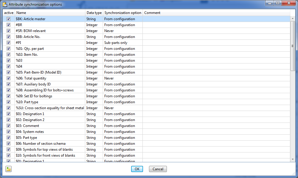
The settings from the file REF3D_ATTR_AKT.DAT for the synchronization of part attributes for referenced parts have been moved to the Configuration Editor (ISDConfigEditor.exe). At System settings > Referencing you can find the find the setting option Synchronization of attributes (SYSTEM > Referencing > RefPartAttrUpdate).
If you click on the  symbol, a window with a table will be opened, enabling you to specify for each part attribute:
 Please note:
Up to HiCAD 2017 the settings for attribute synchronization could be found in the system file REF3D_ATTR_AKT.DAT.
If you want to take over the settings from an existing REF3D_ATTR_AKT.DAT file, this can be done via the Open file  button. After selecting the file, the settings shown in the Attribute synchronization options dialogue window will be overwritten with those of the selected file. Confirm with OK.
If you have customized the REF3D_ATTR_AKT.DAT file, save the file before performing an update!
The settings from the file TXTPAR.DAT have been moved to the Configuration Editor. There, you can find the settings at:
When selecting certain functions, a shaded polyhedron model preview will be attached to the cursor. For instance, this is the case when inserting or transforming parts, inserting new parts in the preview mode, or inserting standard parts.
This preview can be hidden temporarily by pressing and holding down the SHIFT key. This may be useful when working with complex models due to performance reasons. When the key is released, the preview is visible again.
This behaviour can also be inverted by a corresponding setting in the Configuration Editor at System settings > Visualisation > Temporary preview for part placement Possible setting options are:
In shaded views, threads can now be displayed with thread textures or transparent. Which representation is to be used can be set in the Configuration Editor at System settings > Visualisation > Views > Thread representation in shaded views.
The dialogue window for sectional views has been expanded. For Sheet Metal parts you have now the option to specify whether the coating in the sectional view is to be shown or not, by activating or deactivating the Display checkbox beneath Coating in the dialogue window. The coating is displayed in the form of an offset edge, the so-called "coating line". The settings for the representation of the coating line can be found in the Configuration Editor at Drawing > Annotations > Coating line in sectional view.
HiCAD now supports two different itemisation modi:
The itemisation mode to be used is an important property of each model drawing. In the Configuration Editor at System settings > Itemisation > Itemisation mode you can specify which itemisation mode is to be used in new drawings. For older drawings created with HiCAD versions up to HiCAD 2017 you would normally (and logically) use the itemisation up to 2017.
You have now the option to display an overview of welded connections in BOMs. For this to happen, go to Plant Engineering > Bills of Materials in the Configuration Editor and activate the checkbox of the parameter Supplement BOMs with an overview of welded connections.
The display of this overview is only possible in BOMs that have been created with the BOM functions of the Evaluation function group; it is not possible for BOMs in isometries and pipe spool drawings.

Configuration Management (CM) • User Interface (CM)
|
© Copyright 1994-2018, ISD Software und Systeme GmbH |