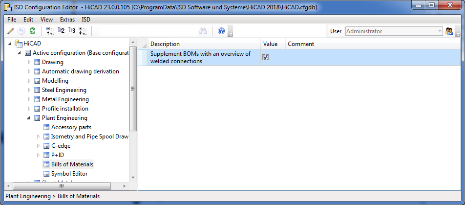
In HiCAD you have the option to display an overview of welded connections in BOMs. For this to happen, go to Plant Engineering > Bills of Materials in the Configuration Editor and activate the checkbox of the parameter Supplement BOMs with an overview of welded connections.
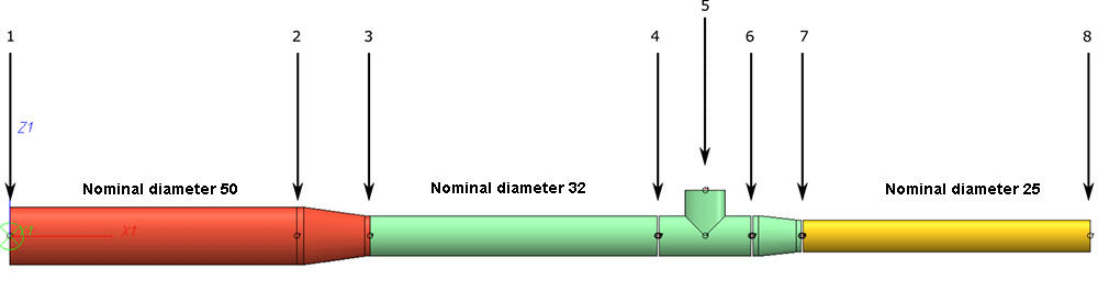
The following example drawing is meant to illustrate the effect of this setting.
The drawing below consists of 3 pipelines with different nominal diameters, which are connected with the help of reducers.
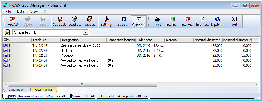
The BOM functions in HiCAD allow you to create BOMs for each individual pipelines, or for the complete model drawing. In the present example, a BOM for the pipeline in the middle, including an overview of welded connections, with the help of the Stückliste für aktive Rohrleitung erstellen  function.
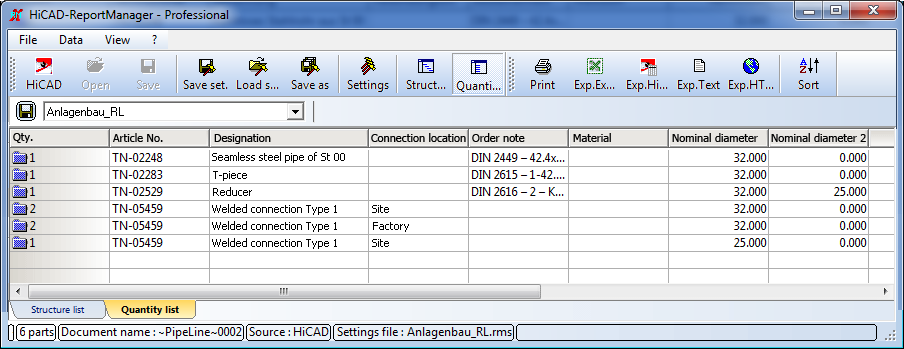
Included in the BOM will be
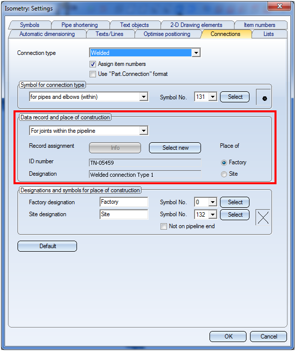
If article number, designation, connection location and nominal diameter are the same, the welded connections will be combined in the BOMs. Article number and nominal diameter originate from the article of the connection, so that welded connections with identical article number will always have the same designation. The article for a connection is specified in the settings dialogue for isometries/pipe spool drawings.
In the default settings the connection location depends on whether a connection exists on the pipeline end or not. In this example the connections 1, 3, 7 and 8 are located on pipeline ends.
If you do not want this distinction to be made, change the connection settings in such a way that connections within and at the end of a pipeline are handled in the same way.
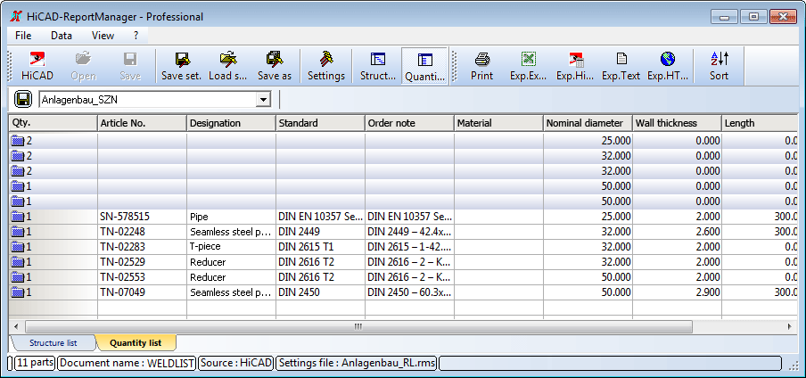
For the pipeline in the middle this will lead to the following BOM:
That is, HiCAD only distinguishes according to nominal diameter.
In the next step, a BOM for the entire model drawing will be created. For this to happen you need to select the Bill of Materials, for the entire drawing  function. The result will look as follows:
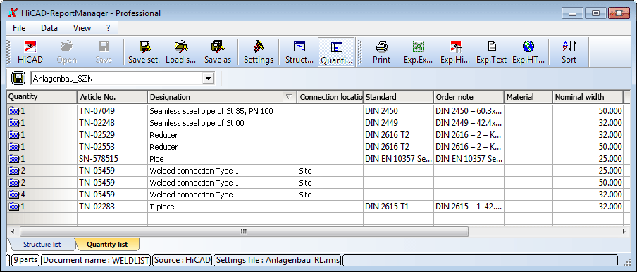
As you can see, the quantity of the welded connections is 8, i.e. the pipelines are no longer viewed separately. Connections 3 and 7 appear in the BOM only once.
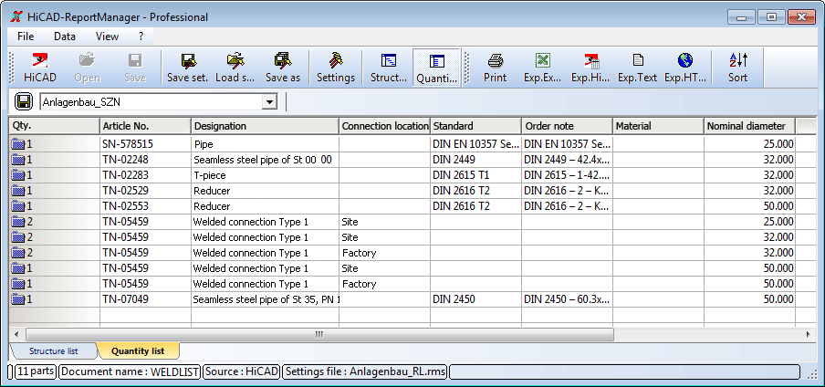
When the separate viewing of the connections at pipe ends is activated, the result will look like this:
If no article has been assigned to the connections in the isometry/pipe spool drawing settings, the following message will be displayed:
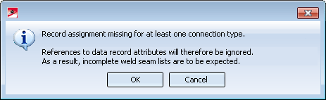
In the resulting BOM the corresponding data will then be missing:
In addition to determining global isometry and pipe spool drawings settings you have also the option to determine individual connection data by means of the Show/change connection info  function.


Plant Engineering Functions • Isometry and Pipe Spool Drawing Settings (PE/Iso) • Connection Info (PE/Iso)
|
© Copyright 1994-2018, ISD Software und Systeme GmbH |