3-D - What's New?

Service Pack 2 2024 (V 2902)
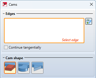
Cams and cam processing
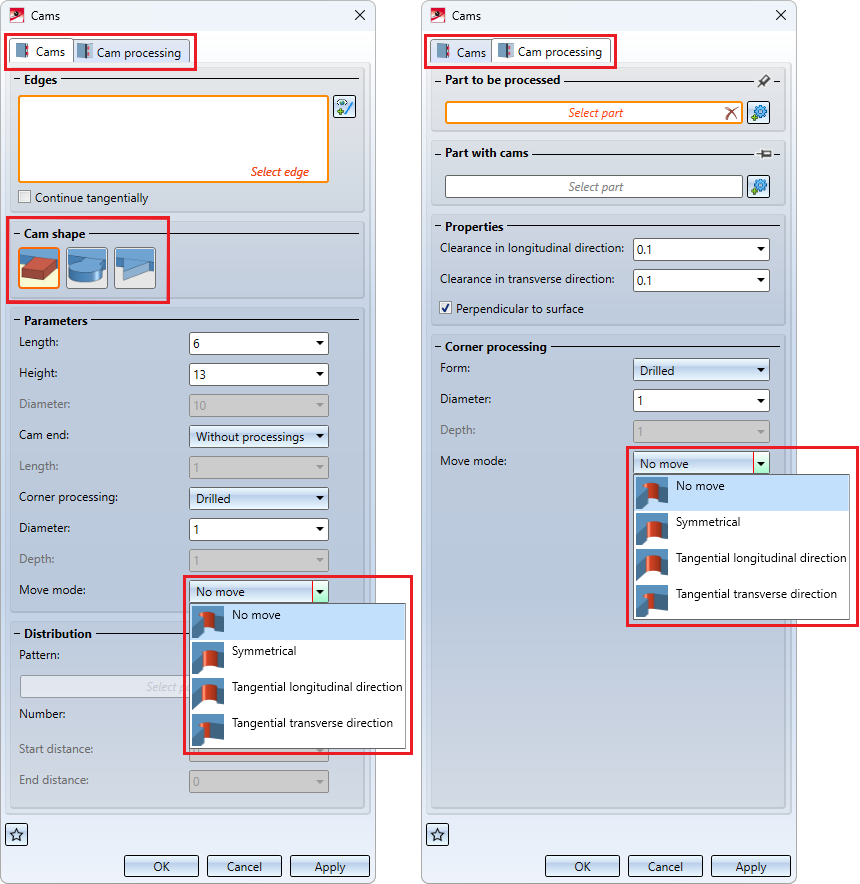
The previous functions Cams and Cam processing have been into one function Cams  .
.
Please note:
Cams and cam processings can be created in one dialogue. However, subsequent processing is only possible separately via the respective feature.
The function has also been extended:
- The settings can be saved as Favourites for later reuse
- The order of the cam shapes has been changed.
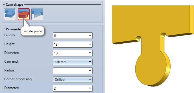
- The Round cam shape has been replaced by the Puzzle piece cam shape.
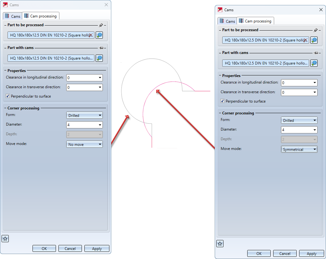
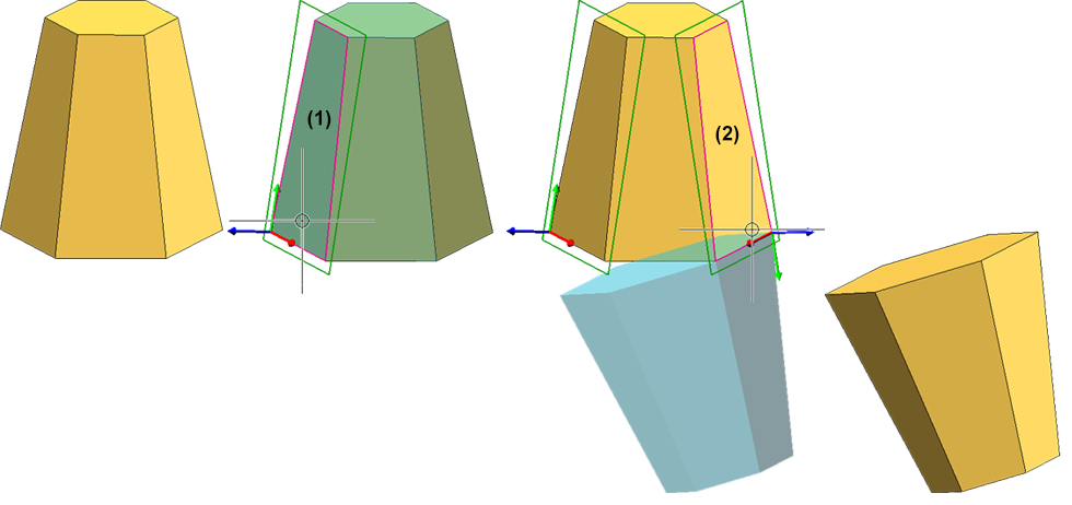
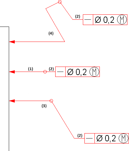
- If Drilled is selected as the corner processing when creating the cam, a move mode can be selected for the cam. This is independent of the selected cam shape. The following options are available:
- No move (1)
The bore is created without moving. The centre of the bore lies at the intersection of the corresponding edges. - Symmetrical (2)
The bore is moved so that it lies symmetrically between the selected edge and the left/right side of the cam. - Tangential longitudinal direction (3)
The bore is moved in the longitudinal direction, i.e. in the direction of the selected edge, so that it is tangential to the left/right side of the cam. - Tangential transverse direction (4)
The bore is moved in the transverse direction, i.e. in the direction of the cam sides, so that it is tangential to the selected edge.

- The move mode can also be selected for the Drilled corner processing when processing cams. The previous settings Move in longitudinal direction and Move in transverse direction.
The move modes can be used, for example, to ensure that bores are not visible after assembly.
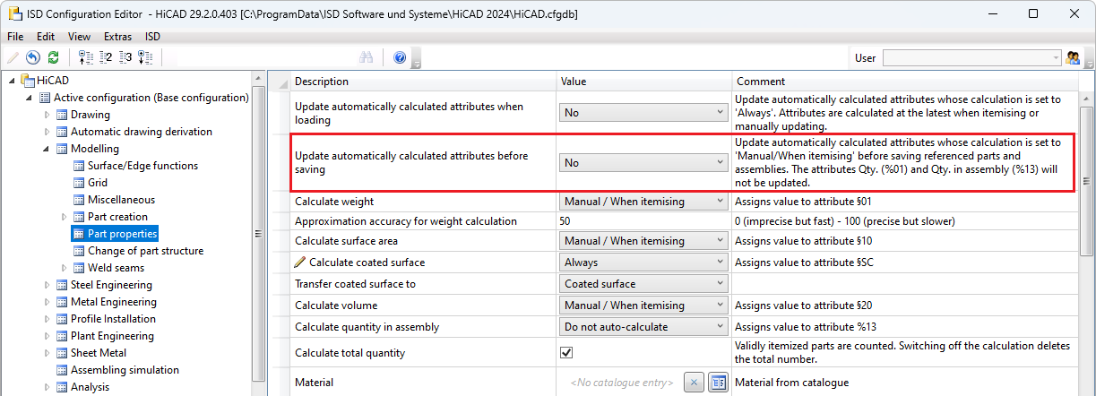
Update automatically calculated attributes before saving
For the calculation of attributes that are set to Manual / When itemising in Configuration Editor, you can specify whether or not these calculations should be performed automatically before referenced parts and assemblies are saved. The setting is made under Modelling > Part properties with the parameter Update automatically calculated attributes before saving. The Weight (§01), the Surface (§10 and §SC) and the Volume (§20) are updated. The attributes Total quantity (%06) and Qty. in assembly (%13) are not updated.
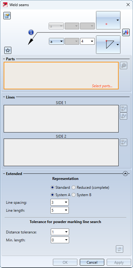
Weld seam marking
With the new buttons in the Weld seams function under Extended, the weld seam can be displayed in accordance with the standard. In accordance with the DIN EN ISO 2553 standard, there are two display options: System A and System B. Previously, HiCAD only supported system A. As of SP2, weld seam marking according to system B is now also possible. In addition, a function for mirroring the weld seam using the annotation tag has been added.
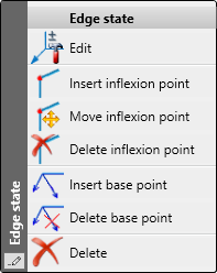
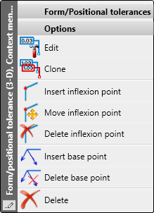
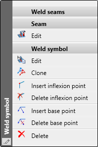
Move and delete inflexion points
The Move inflexion point function can be used to move any inflexion point from form and positional tolerances, chamfer dimensions, weld seam symbols, edge markings and annotation tags. If there are multiple inflexion points, any inflexion point except the last one can be deleted.
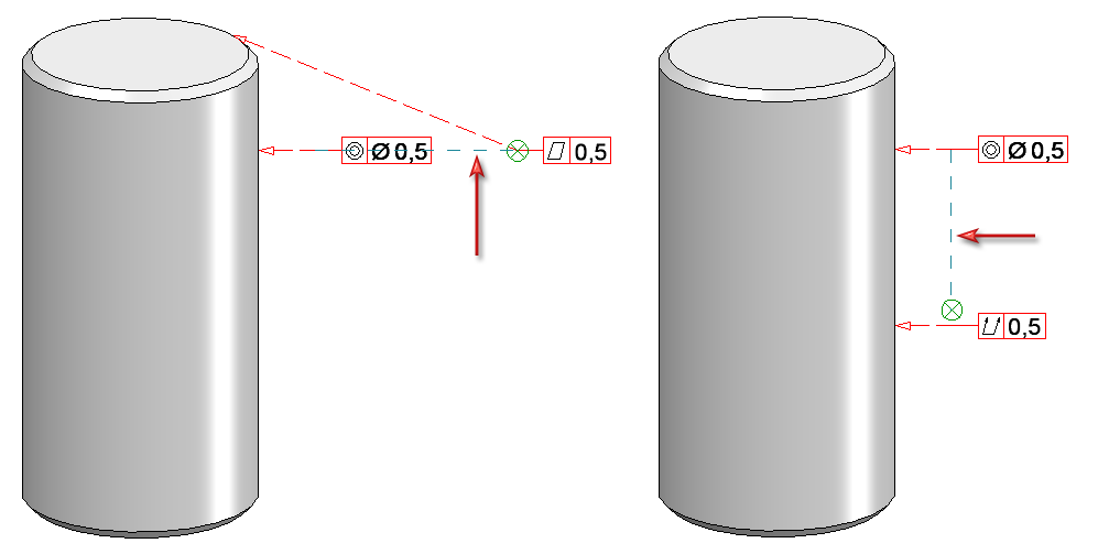
Magnetic snap-in of form and positional tolerances
New form and positional tolerances can be aligned horizontally or vertically to the existing form and positional tolerances in the same view.
If a form and positional tolerance moves at the same height as an existing one during dragging, this is indicated by showing a horizontal auxiliary line in the graphic. When the form and positional tolerance is dropped, it is aligned with this line. This also applies to vertical alignment. After the form and positional tolerance has been itemised, the displayed auxiliary line disappears. The reference point of the tag is used for alignment. If there are no other tags between two form and positional tolerances, parallelism is offered. Magnetic snap-in can be switched off by pressing the ALT key.
Magnetic snap-in of annotation tags
If there are several annotations, the annotation tag to be moved can now be aligned horizontally or vertically with other annotations.
If an annotation tag moves at the same height as an existing tag during dragging, this is indicated in the graphic by showing a horizontal line. If you place the annotation down, it is aligned with this line. The same applies to vertical alignment.
Please note:
This functionality is only used to simplify the alignment of the annotation. The alignment is not associative. This means that the annotation tag is not updated if the tag to which it is aligned changes.
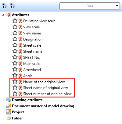
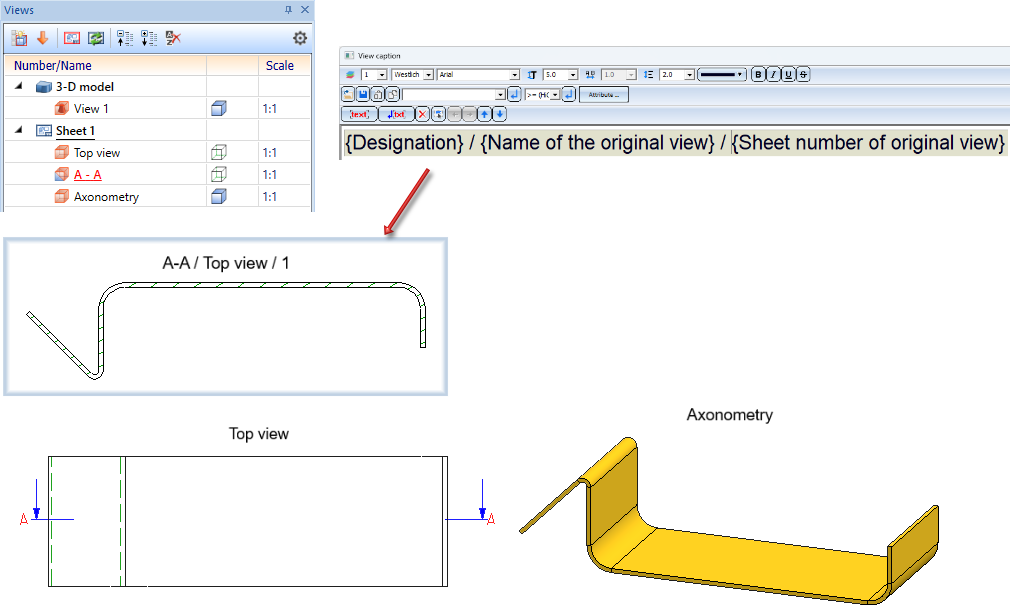
View caption - information on the original view
As of SP2, the name, sheet name and sheet number of the original view can also be used in view captions for derived views, e.g. sectional or detail views.
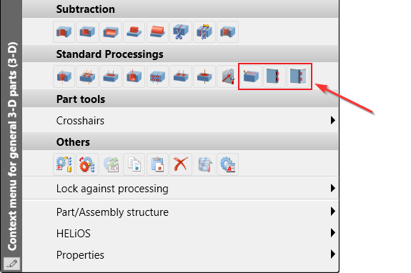
Context menu extension
Two functions have been added to the context menu for general 3-D parts (3-D) under Standard Processings. The functions are Lettering and Cams.
Exact representation of the view selection
If a view with quick representation is active or the current view selection contains a view with quick representation, the Exact representation function is available in the transparent toolbar.

Previously, this function could only be used to restore the exact representation of the active view. As of SP2, this applies to all views of the active view selection.
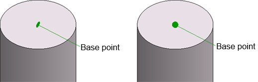
Annotation - Base point symbol
Different base point symbols can be selected for 3-D annotations. From SP2, the Circle and Circle (filled) symbols are always displayed in the screen plane. The symbols therefore remain circular. Up to now, the symbols were spatially consumed, turning them into an ellipse.
Referencing
Updating identical parts
With SP2, the parameters
- Automatically update referenced parts after each change and
- Update identical parts of referenced parts before saving
are available again in the Configuration Editor under System settings > Referencing.
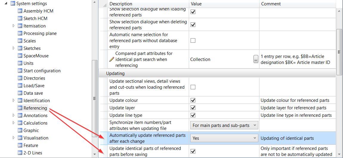
If there are several identical parts of a processed, referenced part in the drawing, the changes are also automatically made to the identical parts if the ISD is set by default. This automatism can be changed with the parameters mentioned above.
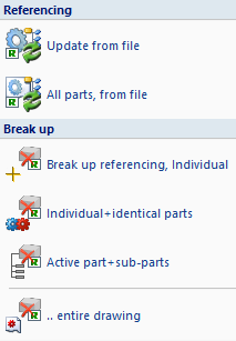
Referencing functions in the ribbon Drawing
The functions
 Update all parts, from file and
 Break up referencing, Active assembly + sub-parts
can now be accessed directly from the Drawing ribbon via the menu of the  Update function. Previously, these functions were only available in the context menu of referenced parts.
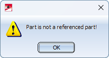
Another new feature is that a message is displayed when the functions
Update referenced identical parts and

are called if the active part is not referenced.
Show/hide elements in view extended
The dialogue of the Show/hide elements in view function has been improved and extended:
-
support for multiple selection,
- saving the settings as favourites,
- transfer of settings from a reference view and
-
simplified operation.
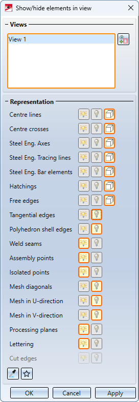
The selected views are listed in the upper part of the dialogue window. After calling up the function, this is initially the active view or the current view list.
To select further views, simply click on the corresponding view frame in the drawing. If the frame of an already selected view is clicked again, the view is removed from the list. Alternatively, views can also be removed from the list by right-clicking on the corresponding entry in the list and then selecting the Remove element(s) from list function.
For the various elements, you can then select whether they are to be
 shown,
 hidden or
 covered in HiddenLine mode.
The selected setting is always indicated by an orange frame.
|
|
Favourites The current settings can be saved as favourites and used again at any time. They are saved in the ProgramData\ISD Software und Systeme\HiCAD 2024\Favourites\VisGUI\ShowAndHideElements folder. |
|
|
Select view from which properties are to be transferred This function can be used to adopt the settings of another view. To do this, select the corresponding view in the drawing. |


The function is also available in the context menu of views and view lists.
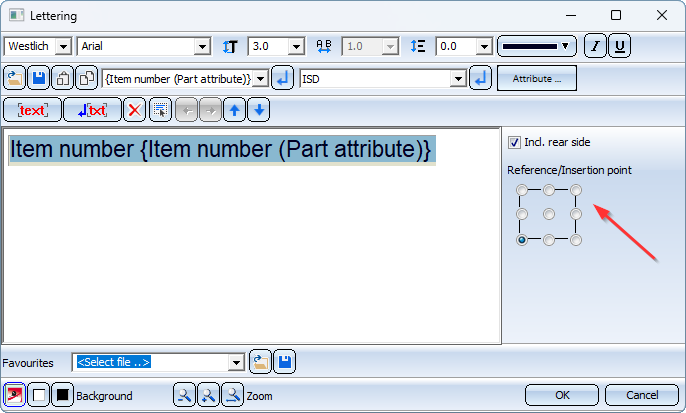
Lettering: Insertion point
In the Lettering function, you can select the insertion point from nine different positions. By activating the desired radio button, you can insert the lettering at this position.
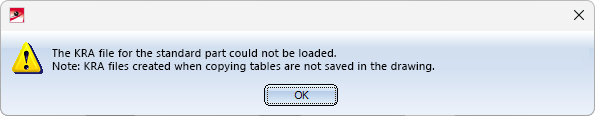
Insertion of standard parts from a copied table
KRA files created when copying tables are not saved in the HiCAD drawing. This means that if you pass the table copy on to a third party, you must also take the corresponding KRA file into account. If a drawing containing standard parts of this table is loaded in HiCAD and the KRA file does not exist, these standard parts cannot be edited with the functions for standard parts. For example, it is not possible to change the display. In this case, an additional message is displayed from SP2 onwards.
Service Pack 1 2024 (V 2901)
Cams and cam processings
The dialogue window of the Cams function has been expanded to include images of the cam shape for better comprehensibility.
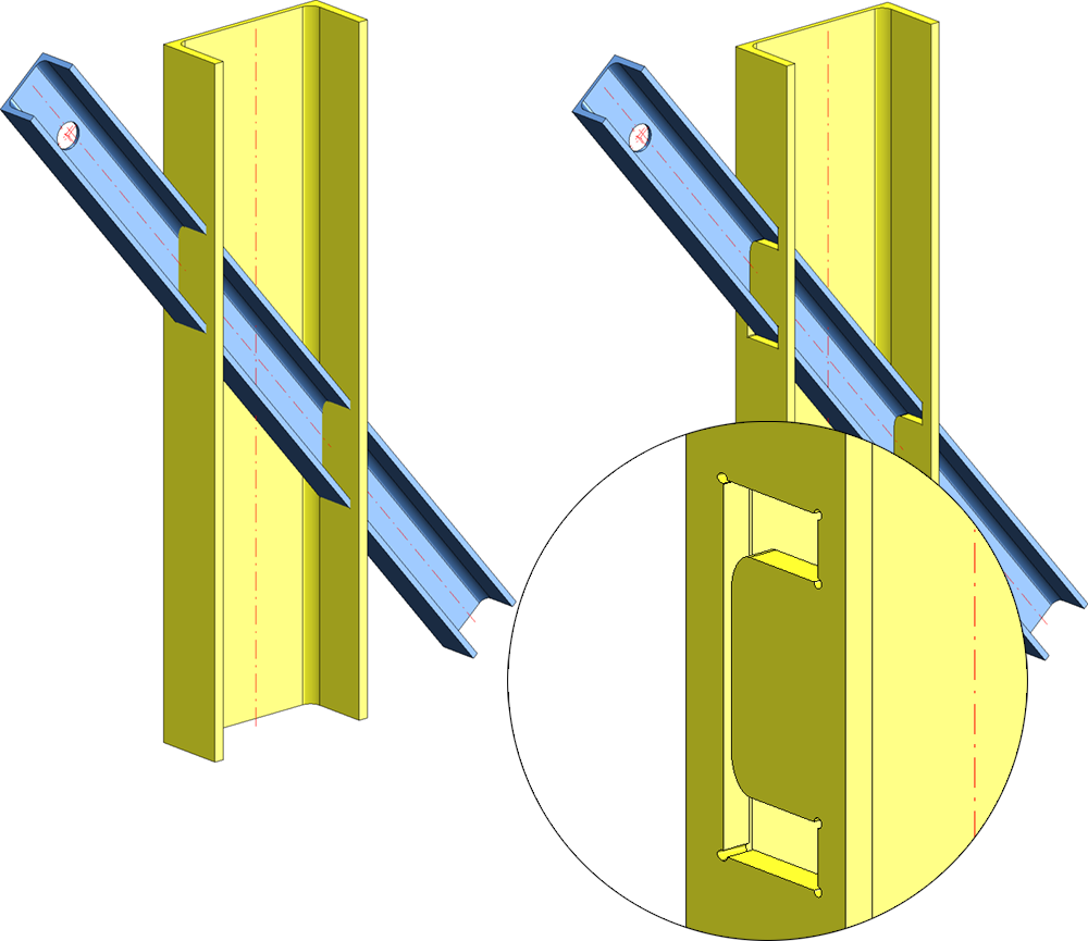
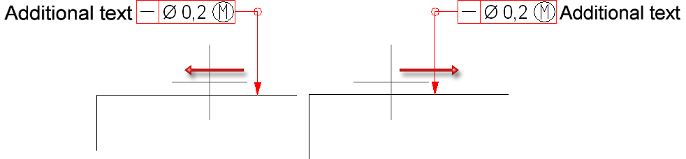
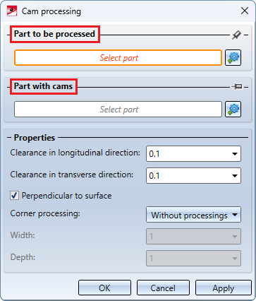
The Cam processing  function now allows you to specify a move in the longitudinal and transverse direction. This is possible if the cam shape is straight and Drilled is selected as the corner processing.
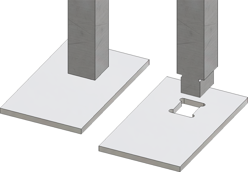
The bores on the part to be processed can then be moved by a value in the longitudinal and transverse direction. The longitudinal direction is the cam direction, the transverse direction is the left/right side of the cam.
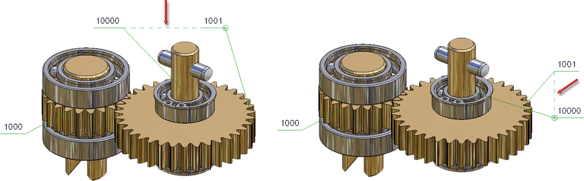
The illustration shows a cam connection. (1) is the part with cams and (2) is the part with the cam processings.
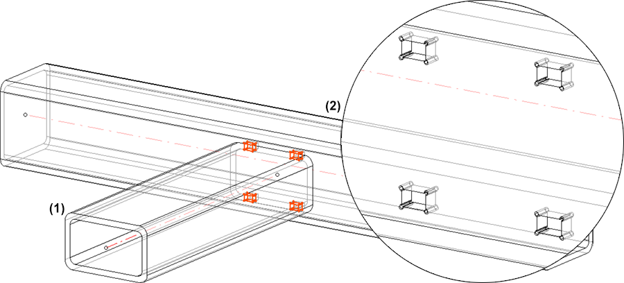
The following figure shows a section of the side view of part (2) - with and without indication of a move.
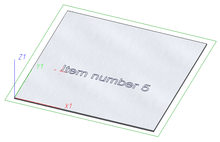
Lettering
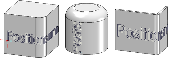
You can use the Lettering function to letter almost any surface. You can now use the lettering function to sign almost any surface. Subtracted from this are cones, spheres and toruses. If the surface has a tangential transition, the lettering continues over the fillet to the next edge. Cylinders are excluded from this. On edge sheets, the lettering continues over the flanges. It is now also possible to create a lettering in the bending simulation.
Replace standard parts
With the new Replace standard parts , you can replace several selected standard parts of one type (e.g. nuts) by selecting a different variant and/or size in the catalogue. If you have created standard parts in a grid and a standard part from the standard part group is in the multiple selection, the entire standard part group is changed.
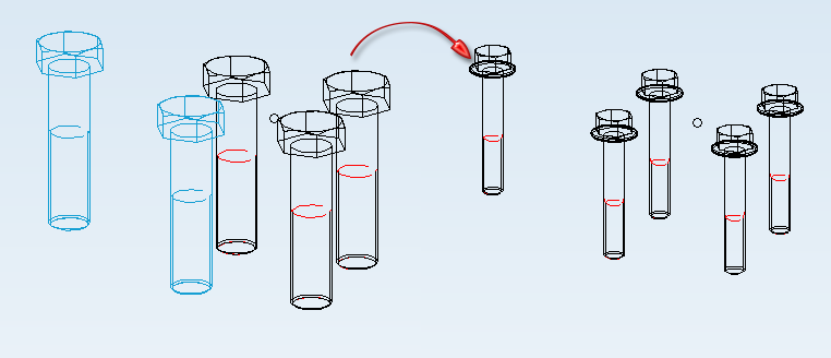
The function can only be applied to standard parts and standard part groups that correspond to the same type (e.g. only screws or only nuts). However, the selection may contain different variants (e.g. hexagon nut and cap nut). If the multiple selection contains standard parts of a standard parts group, the entire standard parts group is changed.
The following options are rejected with an error message:
- Multiple selection with standard parts/standard parts groups that do not correspond to the same type,
-
Multiple selection with parts that are neither standard part nor standard parts group,
-
Standard parts/standard parts groups from design variants and configurators (e.g. in steel engineering),
-
Standard parts/standard parts groups that belong to a bolting,
-
standard parts/standard parts groups with feature log and
-
blocked standard parts/standard parts groups.
![]() Please note:
Please note:
- Processing operations such as bores are not adapted. The Replace standard parts function only allows you to change the standard. Other properties such as the representation of the thread cannot be changed.
- For standard parts with a free value (e.g. the effective length for rivets), this value can be entered. It is then used for all replaced standard parts.
Referencing
Updating identical parts
When externally or internally referenced parts are changed, all identical parts in the current drawing are automatically updated from SP1. The parameters
- Automatically update referenced parts after each change and
- Update identical parts of referenced parts before saving
have therefore been removed from the Configuration Editor under System settings > Referencing.
Referenced assemblies with referenced parts
Referenced parts with changed geometry are always offered for saving when the drawing is saved. This may mean that the KRA file of the part is updated, but that of the assembly is not. When reloading the drawing or inserting the KRA file of the higher-level assembly, HiCAD then detects that the part it contains has a newer KRA version, which is then reloaded.
In practice, there is sometimes a desire for the KRA of the higher-level assembly to always contain the current status of its subordinate parts, e.g. so that the HELiOS document structure always matches the KRA file. As of SP1, it is therefore possible to define how externally referenced assemblies are to be handled when saving drawings and when changing drawings if they contain externally referenced parts.
Various options are now available in the Save referenced parts dialogue window under Parts to be saved.
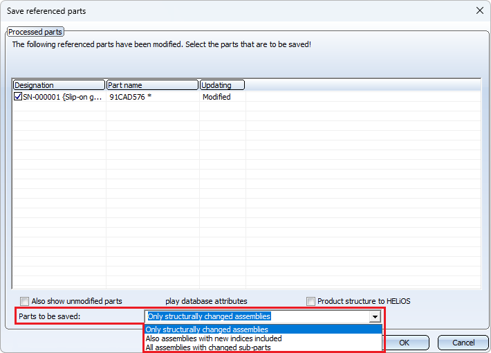
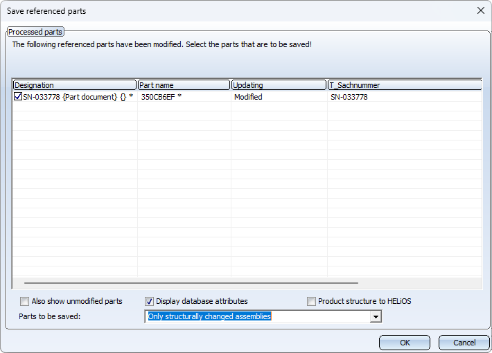
Only structurally changed assemblies
Referenced parts with changed geometry are offered for saving. However, the referenced assemblies to which the parts belong are only taken into account if they have been structurally changed. This is the previous procedure before HiCAD 2024 SP1.
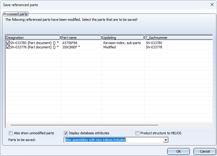
Also assemblies with new indices included
If this option is selected, the assemblies whose directly referenced parts have a new document master index are also offered for saving in addition to the structurally changed assemblies. This option only has an effect if the parts and assemblies are managed in HELiOS.
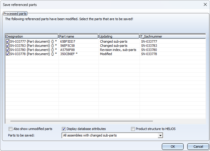
All assemblies with changed sub-parts
If this option is selected, the assemblies that contain changed referenced parts in their entire structure are also saved, regardless of the level. If this option is preset in the Configuration Editor, the corresponding assemblies are marked with the symbol in the ICN.
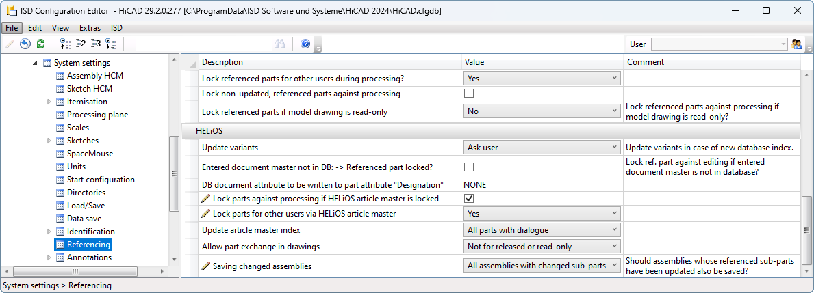
Which setting is active here when saving is determined by the setting in the Configuration Editor under System settings > Referencing > Saving changed assemblies. The ISD default setting is Only structurally changed assemblies. Even if you select a different setting when saving a drawing during the current HiCAD session, the setting from the Configuration Editor will take effect again the next time it is called up.
Example
In the Configuration Editor, the parameter Saving changed assemblies has been preset to All assemblies with changed sub-parts under System settings > Referencing.
The following figure shows a drawing managed in HELiOS with three assemblies BG1, BG2 and BG3. Assembly BG2 is subordinate to assembly BG1 and contains assembly BG3. All assemblies contain different solid primitives. In the first step, both the parts and the assemblies have been referenced externally with the part and document master.
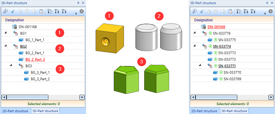
The chamfer length of the right prism has then been changed in assembly BG3 and an index has been created in the document master of the left prism.
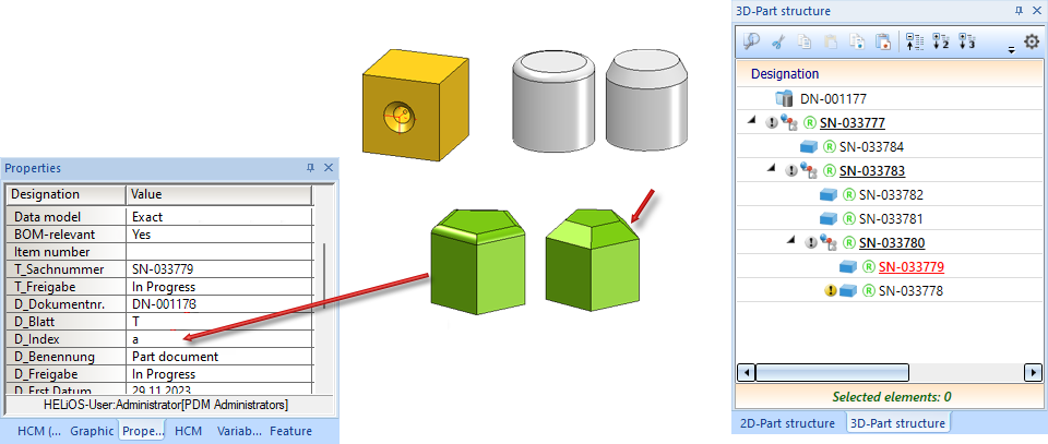
Parts whose geometry has changed - in the example, the right-hand prism - are marked with the  symbol in the ICN. Due to the default setting in configuration management, all assemblies with changed sub-parts are additionally marked with the
  symbol. If the drawing is now saved, all marked assemblies and the prism with the changed geometry are listed in the Save referenced parts dialogue window.
If you change the selection under Parts to be saved,the list of parts changes.
Dimensioning and annotations
Adopt tolerance
The Adopt tolerance  can be used to transfer dimensional tolerances from one dimension to another. To do this, you can click on the reference dimension, i.e. the dimension whose tolerance you want to adopt, to select the tolerance you want to copy. Then click on all the dimensions into which you want to insert the tolerance. To end the function, press the middle mouse button once.
![]() Please note:
Please note:
Brackets or symbols that were assigned to the reference dimension using other functions such as Edit dimension figure or Set symbol are not taken into account during the transfer.
3-D annotation with HELiOS data
As of HiCAD 2024 SP1, HELiOS data is saved in annotations with the drawing. This data is then used when working without HELiOS. This also applies if a different sheet is printed via the plot manager (from HiCAD 2024 SP1) than the sheet active when saving the drawing. Previously, the HELiOS data was missing in the annotation tags in this case.
Please note that this change does not affect existing drawings. These must first be saved again.
Form and positional tolerances (3-D) - Preview window
The background of the active sheet/model area is automatically displayed in the preview window of the form and positional tolerances (3-D). This only changes when the background of the sheet/model area is changed.
Edge state - preview window
The preview window for the edge state (3-D) automatically displays the background of the active sheet/model area and only changes when the background of the active sheet/model area is changed. The font and line colour is also displayed in the preview window.
Clean up intersections - Bore out inner corners
The Clean up intersections  function has been extended.
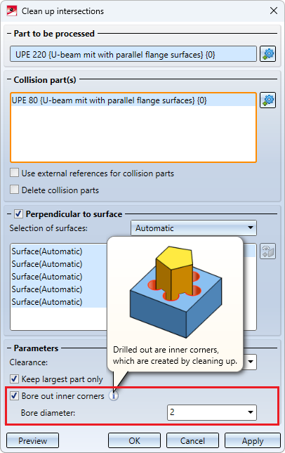
In certain situations, clean-up can result in concave corners. These can now be bored out if required by activating the Bore out inner corners checkbox and specifying a bore diameter. For example, this can be useful for parts with cams that were not created with the Cam function. Another use case is "jumbled" parts, such as the profiles in the following illustration.
Views
Create sectional view - Extensions
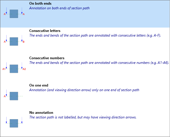
The dialogue window of the Sectional view  function has been expanded in the Ident area on the Parameters tab with the Annotation selection box to include images for better comprehensibility.
Change section path
New in the menu under Views > Edit > Section is the function Change section path  .
.
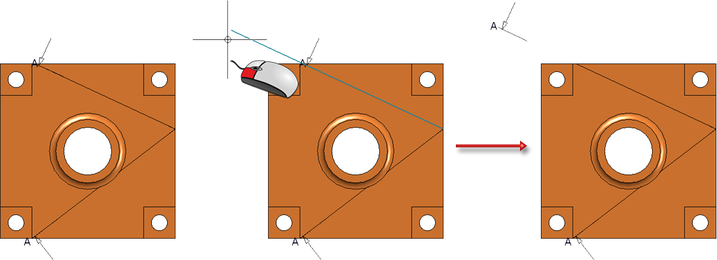
The function can be used to edit the sketch for the section path directly. After calling up the function, the following window is displayed:
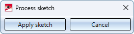
Then edit the sketch using the functions of the Sketch ribbon and finally click Apply sketch. The sectional view is then adjusted directly.
The section path can also be extended later by simply dragging it without having to call up the Change section path function.
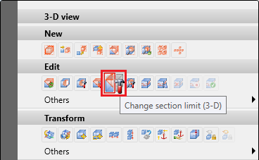
Change section limit
The new Change section limit  allows you to directly change the sketch for the sectional view limit. After calling up the function, you can adjust the sketch as desired. Click on Apply sketch to apply the change.
You can find the function in the Views ribbon under Edit > Section  and in the context menu for views.
Fixed view point when changing scale
Previously, if the view scale was changed, a fixed point had to be set again. From SP1, the fixed point is retained.
Align views horizontally/vertically, via points
The following functions are new in the context menu of views:
|
|
|
|
|


These functions can be used to align individual views horizontally or vertically to a specific point.
-
After calling up the function, first select a point for the alignment. Depending on the function selected, a horizontal or vertical alignment guideline is then shown through this point.
- Then select a point in a view. This view is then moved orthogonally to the alignment guideline so that the point selected in the view lies on the alignment guideline.
Please note that the selected point must belong to a view, otherwise a corresponding error message will be displayed.
The function does not end automatically after it has been executed, i.e. you can align further views to the displayed line by selecting further viewpoints. You end the function with the middle mouse button or with ESC.
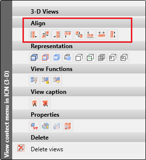
Align and distribute views flush/centred
As of SP1, HiCAD 2024 also offers the option of aligning several views flush (right, left, top, bottom) or centred (horizontal, vertical). In addition, views can be evenly distributed horizontally or vertically. The corresponding functions are available in the context menu for views if a view list (multiple selection) is active.
|
Align |
Distribute |
||
|---|---|---|---|
|
|
Align views left |
|
Distribute views horizontally |
|
|
Centre views horizontally |
|
Distribute views vertically |
|
|
Align views right |
|
|
|
|
Align views at top |
|
|
|
|
Centre views vertically |
|
|
|
|
Align views at bottom |
|
|


Align
With the flush alignment functions, only the displayed geometry is aligned; dimensioning, annotations etc. are not taken into account. This means that the smallest enveloping rectangle is used, which only completely encloses the geometry. The alignment line is determined by the "extremum" of the views. For example, in the right-aligned alignment, the view whose geometry extends furthest to the right remains in place. With the top alignment, the view with the highest geometry point remains in place.
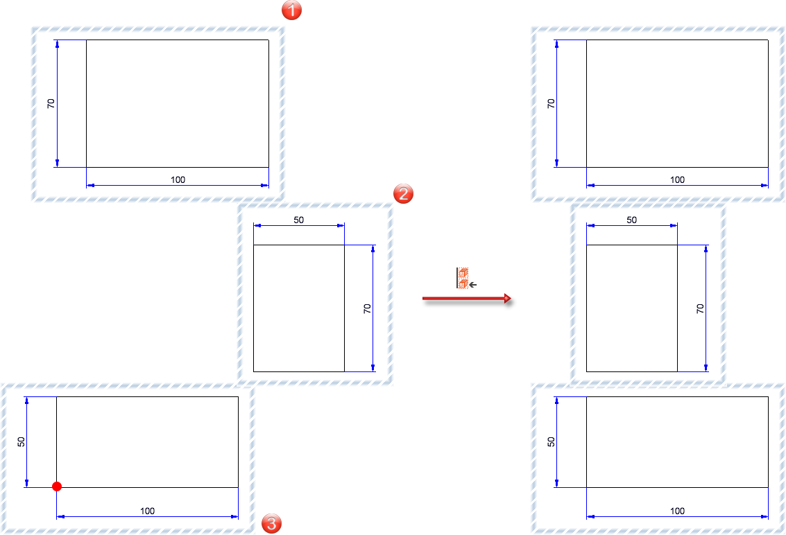
The illustration shows three views, with view 3 projecting furthest to the left. On the right of the image you can see the result with left-aligned alignment. The position of view 3 is retained.
If you want to centre vertically, the alignment line is halfway between the top and bottom geometry points of the selected views. The views are then moved so that their centre lines lie on the alignment line. For horizontal centring, the alignment line is determined accordingly by the points furthest to the left and right of the selected views.
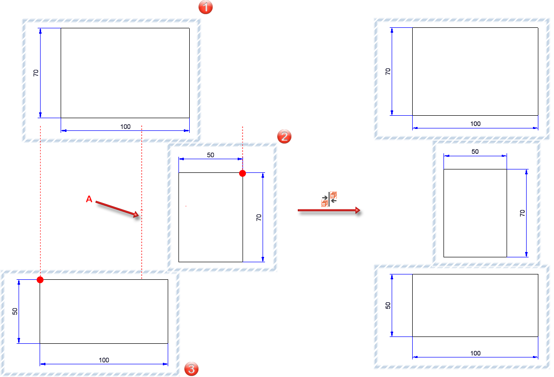
The illustration shows three views, with view 3 projecting furthest to the left and view 2 furthest to the right. A is then the alignment guideline. On the right of the image you can see the result with horizontally centred alignment.
Distribute
In contrast to alignment, dimensioning, annotations etc. are also taken into account when distributing in addition to the geometry. This means that the smallest enveloping rectangle that completely encloses all objects in a view is processed here.
Horizontal distribution moves the views to the right or left so that they are distributed laterally with the same lateral distance to the next view. The two views that protrude furthest to the left and right determine the overall width for the distribution and are not moved themselves.
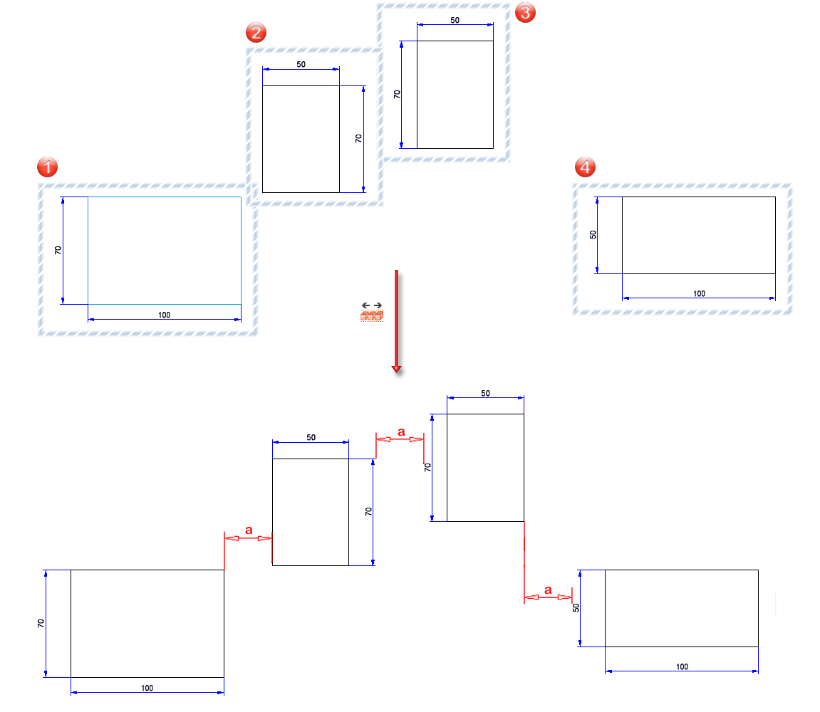
The illustration shows four views that are to be distributed horizontally. Views (1) and (4) remain in place as they project furthest to the left and right respectively. Views (2) and (3) are moved horizontally so that the distance a between all views is the same.
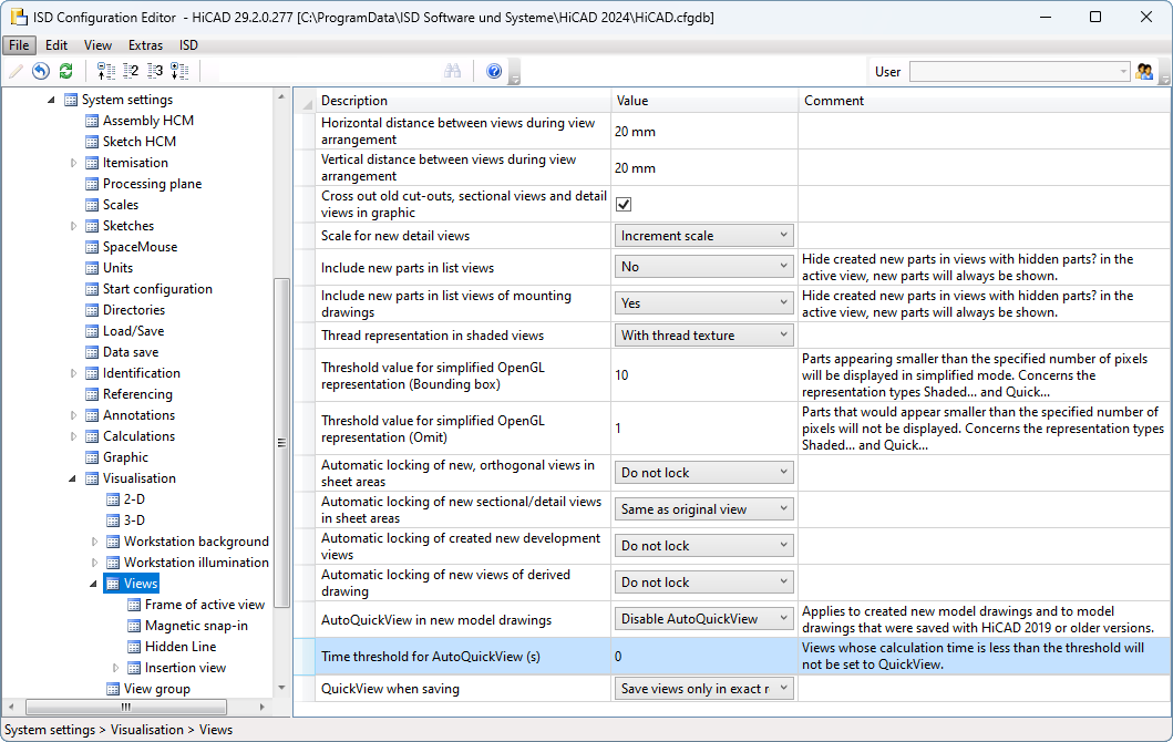
Time threshold for AutoQuickView (s)
A threshold value in seconds can now be specified for the AutoQuickView in the Configuration Editor.
If a threshold value > 0 is specified, the HiddenLine or glass model calculation is aborted if it takes longer than this threshold value. The view is then switched to QuickView. Subsequent calculations of the view no longer start a HiddenLine or glass model calculation, as the view is already in QuickView. The threshold value applies at the respective workstation for all drawings in which the AutoQuickView is switched on.
For example, in workshop drawings, a value of 0.1 to 0.5 seconds could mean that the views of the individual items remain in exact representation and only "large" views of the entire drawing are switched to QuickView.
The ISD default setting is 0, i.e. the QuickView takes effect for every HiddenLine and glass model calculation. This corresponds to the previous behaviour before HiCAD 2024 SP1.
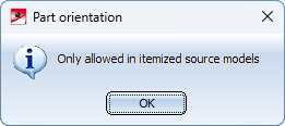
Part and dimension orientation
The Part and dimension orientation can only be defined in drawings that are itemised source models. If this is not the case, a corresponding message is now displayed, e.g.
Transform and clone - Move+rotate via planes
The previous function
 Move+Rotate part, via fitting points has been replaced in SP1
by the function
 Move+Rotate part, via 2 planes.
Use the new function to move+rotate the active object, i.e. it is moved and rotated at the same time. The object can now be either a single part or a part list.
After calling the function, first select a plane on the object and then a plane in the drawing. The parts are transformed so that the coordinate systems of the two planes are aligned.
As soon as the plane in the drawing has been completely defined with the next click, a preview of the transformed part or part list is displayed.
You can find further examples here.
To determine the planes, you can also use the functions of the context menu - just like when drawing sketches.
Similarly, the previous function
 Clone+Move part
has been replaced by the function
 Clone part, via 2 planes
Major Release 2024 (V 2900)
Dimensioning and annotations
3-D annotations - background cut-out
In 3-D annotations, the background cut-out can now be activated either for the entire annotation or for the individual text blocks.
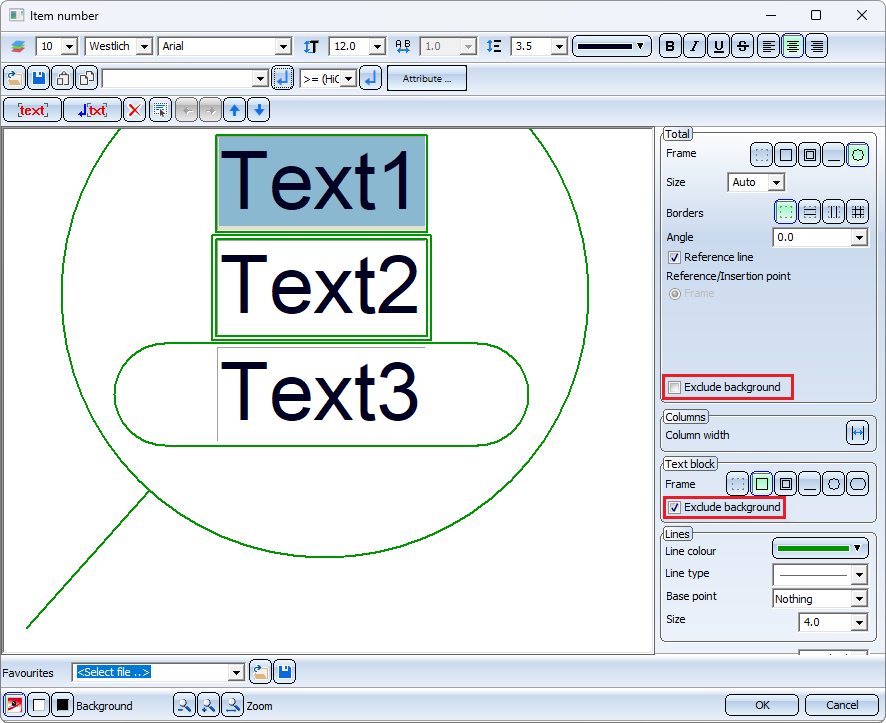
The checkbox for text blocks is only visible if the corresponding checkbox under Total is inactive.
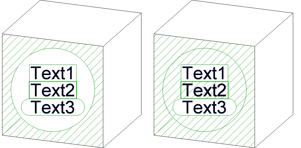
Background cut-out - Left: Annotation, Right: Text blocks 1 and 3
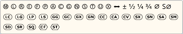
New symbols in the context menus
The symbols in the context menus for annotations and annotation tags have been changed, e.g.
Form and positional tolerances
The new function for form/positional tolerances introduced with HiCAD 2023 has now been extended once again.
New inflexion point
When setting form and positional tolerances, it was previously only possible to insert new inflexion points of the leader line by calling up the context menu (right mouse button) and then selecting the New inflexion point  function. As of HiCAD 2024, this function can now also be called simply by pressing the CTRL key.
Other new features
- The list of available symbols has been extended.
- The wrap-around symbol is now placed at the last inflexion point. If a reference line does not have an inflexion point, the wrap-around symbol is placed between the reference line (1) and the tying line (2).
- Flags with a reference symbol can also be set at form/positional tolerances. The reference flag can then only be set at the top and bottom. If the form/positional tolerance is moved, the reference flag is also moved.
- The additional text of a line in form/positional tolerances changes the side when the side (right/left) of the form/positional tolerance changes.
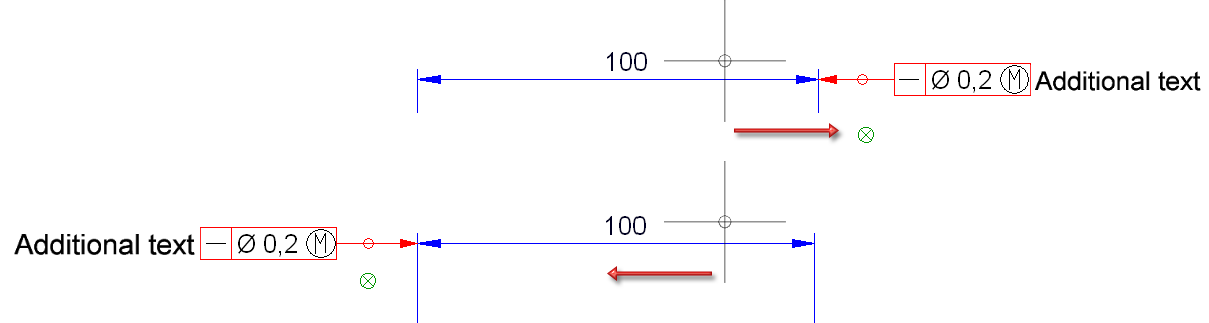
- Form/positional tolerances can be set at projection lines. If the dimension is moved, then the tolerance is also moved.
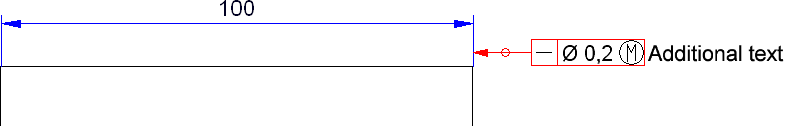
- If a tolerance is set to the dimension line of a distance or diameter dimension, then flag is no longer rigidly attached to the dimension line. By dragging the arrow, the reference point can also be set to the other side of the dimension.
- The context menu for form/positional tolerances has been adjusted to that of annotations.
Simplified orientation of the dimension figure
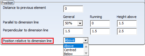
Previously, the dimension number could only be defined by the distance to the dimension line. As of HiCAD 2024, it is now also possible to arrange the dimension number in a simplified way by selecting the desired option
- below or above the dimension line or
- centred on the dimension line.
For this purpose, the Dimension figure tab has been extended in the dimension parameter settings for interactive dimensions as well as for HCM and parameter dimensions.
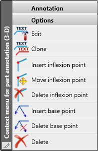
3-D part annotation - Insert base point
With the Insert base point  function, which you can find in the context menu of a 3-D part annotation, you can now directly add several base points to the selected annotation. You end the base point input with the middle mouse button.
Coating of general parts
Up to now, the coating of general parts (without structure) was not displayed in sectional and detail views. In addition, coating was not possible if these parts were part of a sectional or detail view.
As of HiCAD 2024, the coating of general parts (without structure) is also displayed in sectional and detail views.
Feature in part creation
In the part creation function dialogues, the Feature checkbox is no longer available as of HiCAD 2024. This means that a corresponding feature is now always generated during part generation.
This affects the following functions:
![]() 3-D Standard > New > Extruded solids
3-D Standard > New > Extruded solids
 3-D Standard > New > Primitive

![]() 3-D Standard > Process > Wall > Envelope
3-D Standard > Process > Wall > Envelope
 3-D Standard > Clone > Param.
 3-D Standard > New > Revolved
 3-D Standard > New > C-edge sweep
Sketches
Simplified rotation of 3-D sketch elements
To simplify the determination of the rotation axis when rotating elements of a 3-D sketch, after selecting the sketch elements to be processed and determining the first point for defining the rotation axis, the active coordinate system is displayed, e.g.
![]()
(1) Selected sketch element, (2) 1st point for rotation axis, (3) Display of the coordinate system.
This affects the following functions:
 Sketch > Transform > Move > Move+Rotate

 Sketch > Clone > Move > Move+Rotate

Marking of sketches with deactivated HCM
If a sketch is active for which the automatic assignment of HCM constraints has been deactivated, this is now indicated in the HCM window of the ICN with a corresponding message.
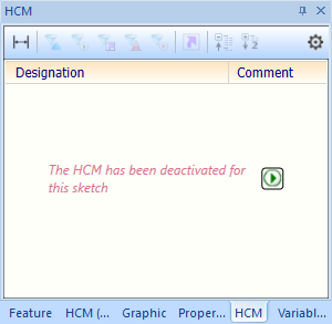
With a click on  the HCM can be activated again, i.e. HCM constraints are automatically assigned to subsequently created elements of the sketch - if possible.
Weld seam and weld symbols
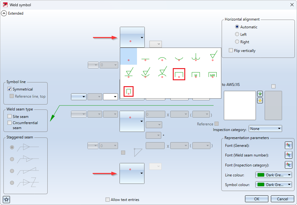
Extended weld symbols
Additional weld symbols are available for symbolic representation on both the reference and opposite sides:
|
|
Weld pool fuse (not specified) |
|
|
Fusible inlay |


Reference line boundary arrow for 3-D weld seam symbols
When processing a 3-D weld seam symbol, the current settings from the Configuration Editor under Drawing > Annotations > Weld symbols were previously always used for the boundary of the reference line.
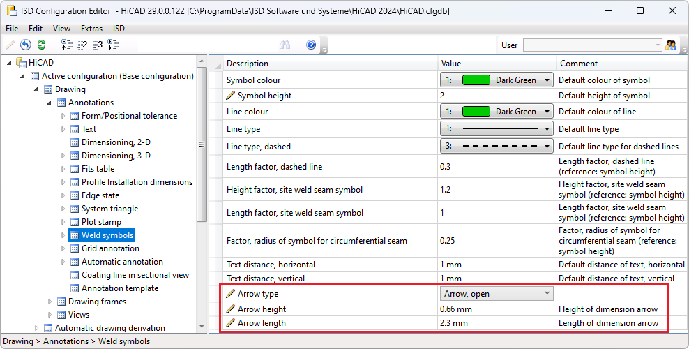
This could result in the display of the boundary changing, for example, when moving or copying. As of HiCAD 2024, the settings for the boundary of the reference line are saved directly to the weld seam symbol. This means that the limitation of existing weld seam symbols is not changed when the corresponding parameters are changed in Configuration Editor.
Show/hide weld seams by view
The functions
 Hide part list in view selection
 Show part list in view selection, hide all other parts and
 Show part list in view selection
are now also available in the context menu for weld seams. This allows single or multiple seams to be shown/hidden in certain views.
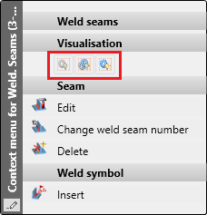
New symbols in the context menus
The symbols in the context menus of welds have been changed.
Views
Magnetic snap-in when moving
Magnetic snap-in of views is now supported when moving views. This procedure allows easy alignment with other views or with the optional additional elements of the drawing sheet (drawing frame, title block and BOMs).
- The view edges can be aligned to be flush with each other or with the additional elements of the drawing sheet. If, for example, during dragging a view moves to the same height as an existing view or one of the additional elements, this is indicated in the graphic, e.g. by fading in the horizontal line. If you put the view down, it is aligned with this line. The same applies to vertical alignment.
-
Equal spacing does not refer to the geometry but to the view rectangle, i.e. the "envelope rectangle" that completely encloses the view including the annotations etc.
a-c: alignment lines left, centre, right, d: distance line
As soon as a corresponding constellation is created when dynamically moving a view/view list, graphical help elements such as distance arrows or orientation lines are displayed. Equal distances are numbered. By means of these lines the view can be aligned and the desired position can be taken over by lowering the cursor. While moving, the selected view is only displayed as an envelope rectangle.
Magnetic snap-in is automatically active when moving with the Move view function and when moving using drag&drop.
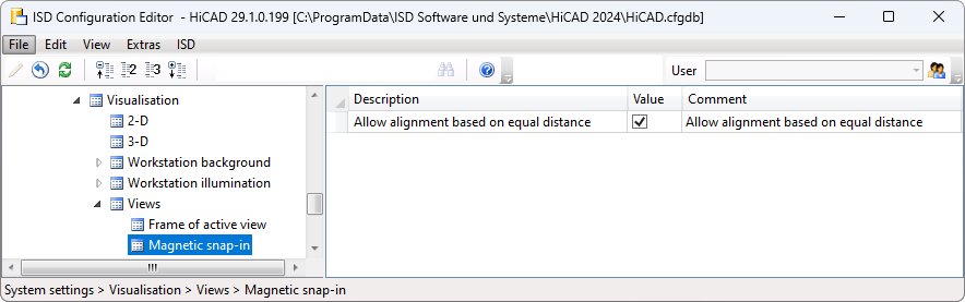
Magnetic snap-in can be switched off in the Configuration Editor. To do this, under System settings > Visualisation > Views > Magnetic snap-in, deactivate the Allow alignment based on equal distance checkbox.
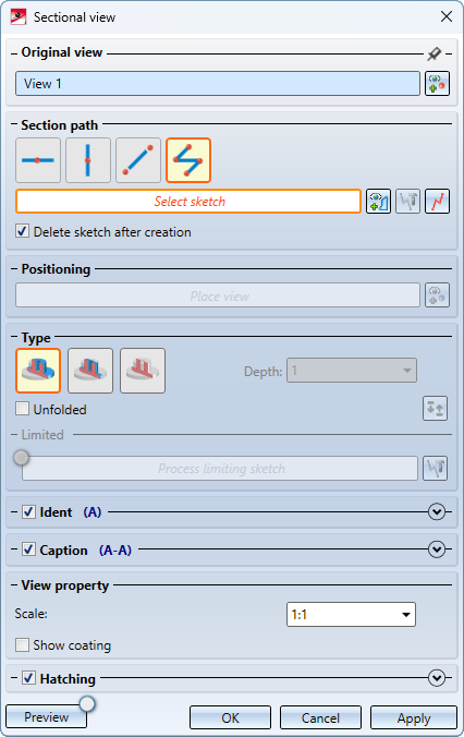
New dialogue for sectional views
The dialogue for creating and processing sectional views has been completely revised.
In addition, the course of a sectional view can now also be changed subsequently without having to call up the sectional view dialogue again. The

function is available for this purpose. You will find the function in the context menu of the annotation (right mouse button) in the original view.
Multiple selection of views
Until now, it was only possible to select multiple views in the ICN. This can be useful, for example, if you want to change the display of several views in one step. As of HiCAD 2024, this is now also possible in the graphics area of the drawing. To do this, hold down the CTRL key and select the desired views. All selected views are marked by a dashed view frame. If a view that has already been selected is selected again, then it is removed from the view list.
Rotating views
When rotating views with the mouse, the rotation point is displayed as of HiCAD 2024. If the rotation point is determined automatically with the middle mouse button, it is also displayed.
3-D rotation point
Deleting dimensions in shortened views
If dimension base points are present in the shortening area when shortening views, then from HiCAD 2024 you can select whether the corresponding dimensions should only be hidden or deleted.
If such dimension base points are present, HiCAD will first display a corresponding message.
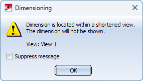
This message can be switched off for the current HiCAD session by activating the Suppress message checkbox. Click OK to continue the function.
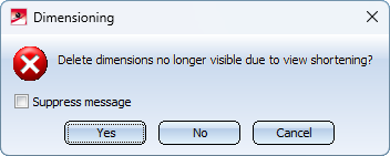
Clicking Yes deletes the dimensions with base points in the shortening area. If you click No, the dimensions are only hidden. If the shortening is deleted, then these dimensions are visible again.
If the Suppress message checkbox is active, the selection of Yes or No applies to the current HiCAD session. The query will then only be displayed again after a restart.
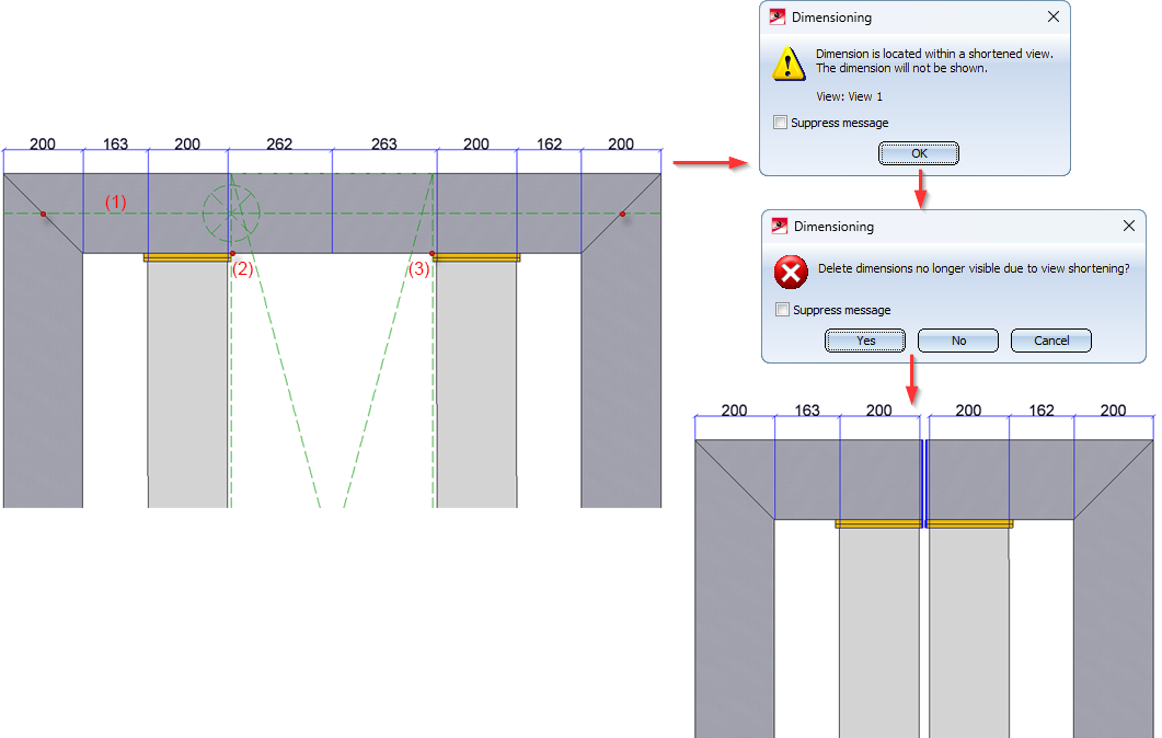
Left: Initial view with shortening axis (1) and division points (2), (3), Right: Result
Temporarily deactivate view shortening
View shortening can now be temporarily deactivated. This can be useful, for example, to view or edit dimensions that are in the shortening area. You can find the functions under Views > Edit > Shorten as well as in the context menu for views.
|
|
Temporarily deactivate view shortening The shortening of the active view is temporarily deactivated, i.e. the view is displayed unshortened until the deactivation is removed. The deactivation is saved with the drawing, i.e. if the view shortening is deactivated when saving, it will also be deactivated when the drawing is reopened. |
|
|
Cancel temporarily activation of view shortening This function cancels the temporary deactivation of the active view. The view is displayed shortened again. |


Consideration of intrusions in Hidden Line representations
Up to now, only intrusions/collisions found between straight lines and planes or those involving circles and cylinders were taken into account in Hidden Line calculations.
As of HiCAD 2024, all collisions with analytical curves/surfaces or with NURBS curves/surfaces are now also taken into account.
What exactly is taken into account can be defined in Configuration Management under System settings > Visualisation > Views > Hidden Line > Collision check.
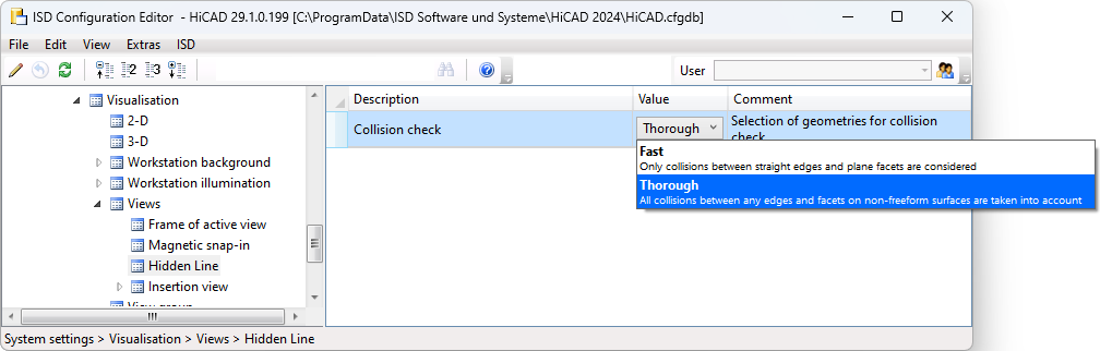
Fast
Only collisions between straight edges and plane facets are considered.
Thorough
With this setting, all collisions between any edges and facets on non-freeform surfaces are taken into account. This is the ISD default setting.
Cams and cam processings
The controls and dialogues for cams and cam edits have been slightly changed.
- When creating cams, multiple edges can now be selected in the selection list of the Cams dialogue window so that you can provide them with the same cams. This means you no longer need to make the settings for each individual edge. Alternatively, you can set the parameters for shape and distribution first and then select the edges.
- In the Cam processing dialogue window, the dialogue texts have been adapted.
- Processings that are not perpendicular also go all the way through.
- Both dialogue windows can be resized.
Update automatically calculated attributes when loading
In the Configuration Editor you can now define whether the dimensions/attributes for which the automatic calculation is activated there should be updated automatically or not when loading a drawing. Read the information on this under Basics - What's New?.
Extensions in lettering
The extensions in lettering allow you to insert attributes, save favourites and control the display in the view.
- Attributes
Attributes can be easily copied from the list box. Select the attribute and click OK. There are some restrictions. Attributes of superordinate parts may not be used. The lettering text must not depend on the position in the part structure. If the part is referenced, only attributes that are transferred via referencing may be used. This can be set in the Configuration Editor under System settings > Referencing > Area: Updating.
Examples of non-permitted attributes: The attribute Benennung 2 is configurable, i.e. non-permitted attributes can be used. The attribute Positionsindex is not permitted because parts with the same position number can have different item indices.
- Multi-line signatures
You can now enter multi-line texts in the text editor of the lettering.
- Save settings as favourites
Letterings can be saved as favourites. The file format is *.FTD. In the HiCAD SYS directory you will find various FTD files with predefined lettering.
- Showing and hiding letterings
The lettering can be shown or hidden in the view. To do this, right-click on the view frame and select the function Show/hide elements in view.