Clean Up Intersections
3-D-Standard > Process > Add > Clean up intersections 
Sheet Metal > Further functions > Extras > Clean up intersections
With this function, collision parts, i.e. parts that cut through the active part, can be subtracted from the active part. If required, you can specifically define which surfaces should be taken into account during the clean-up. This can be useful, for example, if flanges or bend zones of a sheet metal part should be excluded from processing. Furthermore - in contrast to the normal subtraction - you can select the surfaces of the active part to which the hole created by the intersection should be perpendicular.

- Part to be processed
- Collision part(s)
- Perpendicular to surfaces / Selection of surfaces
- Parameters
- Executing the clean-up

Part to be processed
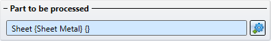
When the function is called, the active part is automatically the part to be processed. You can change the selection by clicking on  . Please note that the entire part is always processed. For example, if the intersection passes through several flanges of a sheet, all flanges and bend zones are automatically processed. However, you have the option of subtracting individual surfaces from the processing in the Selection of surfaces.
Collision part(s)
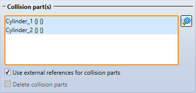
In the Collision part(s) area, click to select the parts or assemblies that are to be subtracted from the part to be edited. The selected parts are listed in the window and highlighted in colour in the drawing. To remove parts from the list, right-click on the part in the list and select the Remove element(s) from the list function. Alternatively, you can also use the DEL key. If an already selected part is selected again, it is automatically removed from the list.
|
Use external references for collision parts |
If this checkbox is active, changes to the collision part are tracked. This means that if you later change the radius of a intersecting cylinder, for example, the subtractions are adjusted accordingly after a recalculation of the Clean up intersections feature. |
|
Delete collision parts |
If this checkbox is activated, the collision parts are deleted after the function has been executed. It is then not possible to use external references. |
Perpendicular to surfaces / Selection of surfaces
The intersection does not have to be perpendicular to the surface, but can also run parallel to the collision parts.
The image below shows a cylindrical collision part (1) that intersects with a pipe. Image A shows the result vertically cut with clearance. The outer surface (2) and the inner surface (3) of the pipe have been selected. Image B shows the result without perpendicular cut.
This can also be useful for sheets for lasers that cut at an angle.
(1) Intersection parallel to the collision parts, (2) Perpendicular to the surface
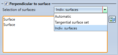
Selection of surfaces
There are several options available to you when selecting the surfaces:
|
Automatic |
Here, all surfaces of the part to be processed are checked for intersections by the collision parts. All surfaces with intersections are transferred to the surface selection. |
|
Tangential surface set |
After selecting a surface, all tangentially adjacent surfaces from the part to be cleaned up are checked for intersections. |
|
Indiv. surfaces |
Here you select the surfaces to be processed individually. You can select additional surfaces later by clicking on To remove parts from the list, right-click on the part in the list and select the Remove element(s) from the list function. Alternatively, you can also use the DEL key. If an already selected part is selected again, it is automatically removed from the list. |
 .
.
The number of surfaces selected has a significant influence on the calculation time. This means that the accuracy of thin-walled 3-D parts - such as hollow cylinders - does not deteriorate if only one surface (inside or outside) is selected.
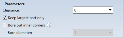
Parameters
Various parameters for processing can be set here.
|
Clearance |
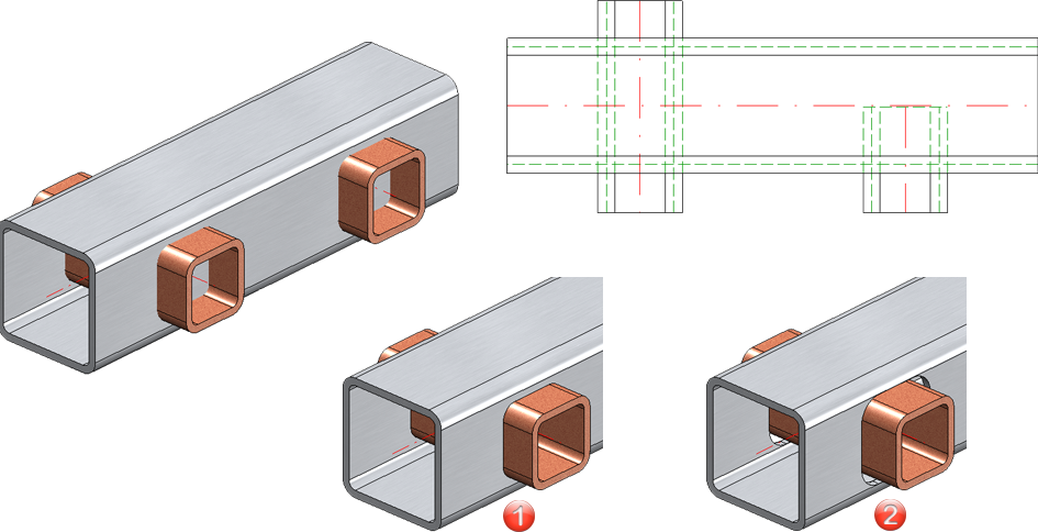
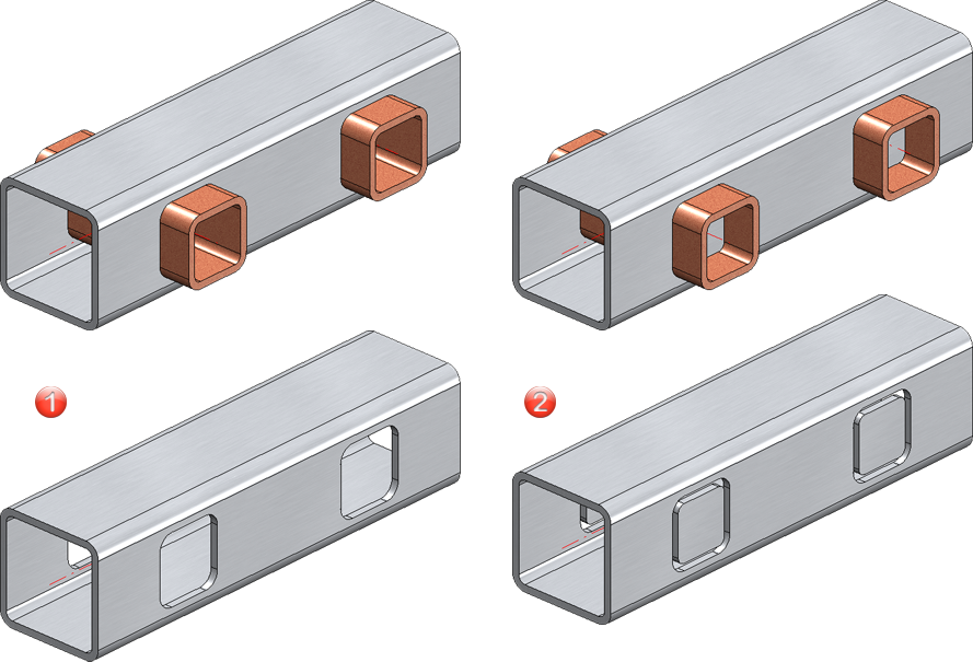
The clearance determines the distance between the intersection and the collision part. In the following example, a hollow profile is penetrated by two other hollow profiles. (1) shows the result without clearance, (2) with clearance.
|
|
Keep largest part only |
By default, only the largest part of the penetrated part is kept after the clean-up. If you also want to keep the small parts, the option can be deactivated. The figure shows the result and the processed part. In case (1) only the largest part was retained, in case (2) all parts were retained.
|
|
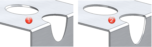
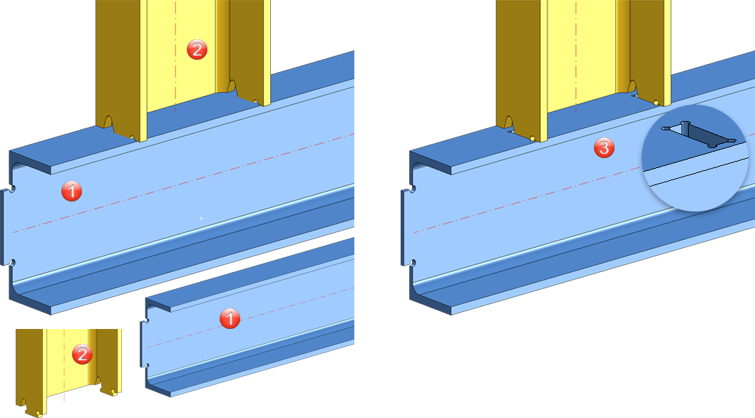
Bore out inner corners |
In certain situations, clean-up can result in concave corners. If required, these can be drilled out by activating this checkbox and specifying a hole diameter. For example, this can be useful for parts with cams that were not created with the Cam function, e.g. as shown in the following illustration. Profile 1 is the part to be processed here, profile 2 is the intersecting part.
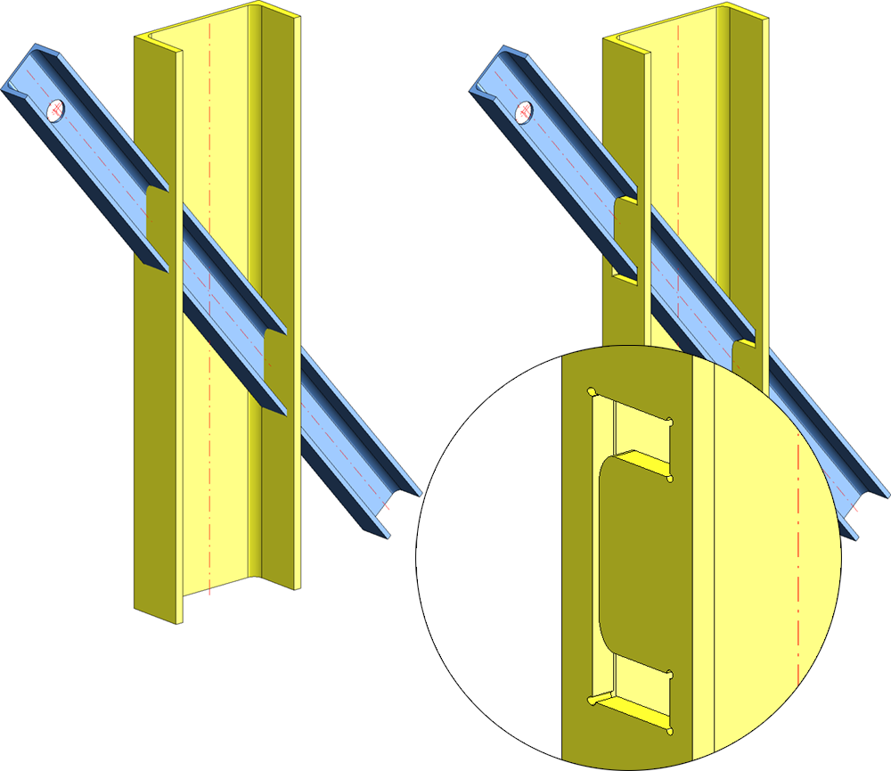
Another application is intersecting parts, such as the profiles in the following illustration. Perpendicular processing has been selected here.
|
Executing the clean-up
You can use the Preview button to check your settings and change them in the dialogue if necessary.
Once you have entered all the required data, the intersections can be cleaned up. Click on Apply or press the middle mouse button to execute the clean-up. The dialogue window remains open so that you can clean up intersections on other parts without having to call up the function again. Click OK to close the dialogue window after the clean-up.
If you exit the dialogue window with Cancel, the function is cancelled without clean-up.
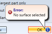
If a clean-up is not possible with the current settings, this is indicated in the dialogue window by the symbol  on the OK button. The selection or input causing the problem is also marked with
  in the dialogue window. If you point the cursor at one of the symbols, a corresponding explanation is shown, e.g.