
The dialogue window
Views> New >
Sectional view 
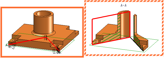
Sectional views can be created in HiCAD in a wide variety of ways, for example, unfolded, with a lateral boundary, with or without marking of the section path, and more. The basis for the section path is a straight line or a sketch.
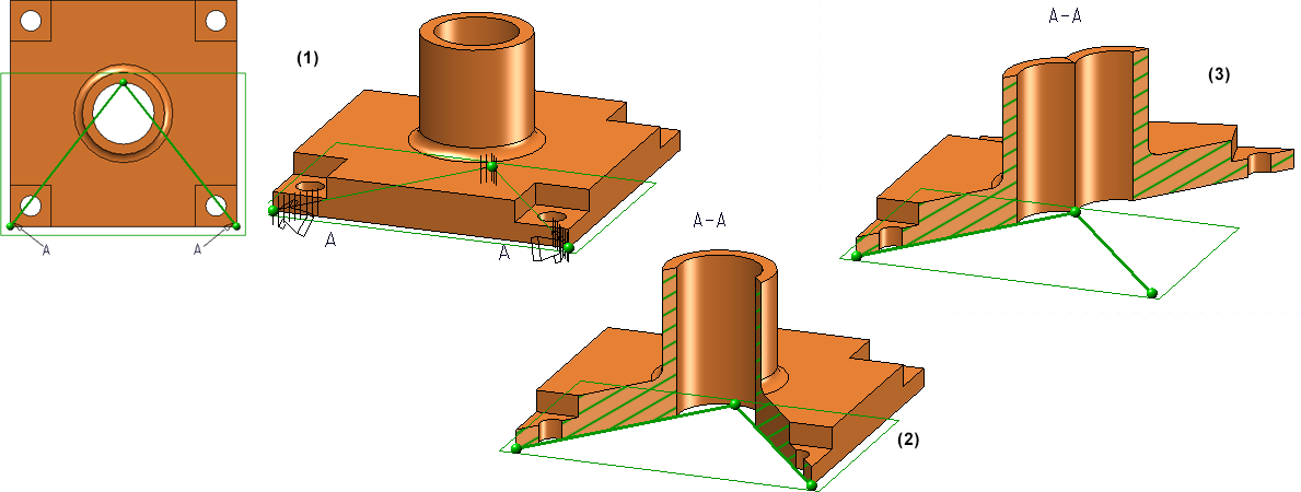
(1) Original view in top view and axonometry with sketch, (2) "normal" section, (3) unfolded section
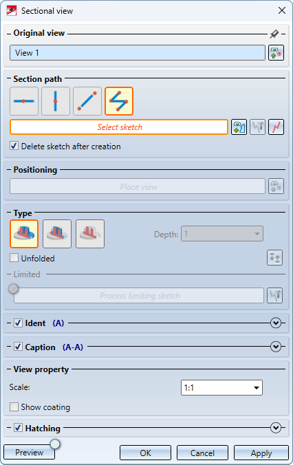
You define the settings for sectional views in the Sectional view dialogue window.
Proceed as follows:
- Select the original view.
- Determine the section path.
- Place the sectional view.
- Select the desired type.
- Set the options for identification of the section path.
- Set the options for the view caption.
- Specify the scale of the sectional view.
- Select the desired settings for the hatching.
- Check the section view with the Preview button and correct your settings if necessary.
- Click Apply, to generate the sectional view as shown in the preview.
Section views are marked with the  symbol in the ICN.
The window areas
Original view
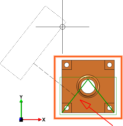
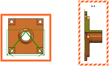
When the function is called, the active view is preset as the original view. The selection can be changed by clicking on  . The original view is marked in the preview with an orange frame.

Section path and positioning
The course of a sectional view is always based on a planar sketch. This can be present in the drawing or it can be created during the definition of the view. The following alternatives are possible:
|
|
Horizontal and vertical cutting line A horizontal or vertical cutting line is displayed at the cursor (horizontal/vertical refers to the XY plane of the active coordinate system). You then define the cutting position with a point determination. As long as the dialogue window is not left, the position can be changed after a click on the HiCAD calculates the length of the cutting line to match the sectioned view. |
|||||||||||
|
|
Diagonal cutting line Here you can select an existing edge in the drawing as the cutting line or define the cutting line by determining two points - for example, the centres of the bores. After determining the first point, the line hangs on the cursor. Then determine the second point. HiCAD calculates the length of the cutting line to match the sectioned view. |
|||||||||||
|
|
Sketch In this alternative, the section course is determined by an arbitrary sketch.
|
|||||||||||


 symbol.


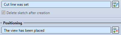
Once the cutting line is set, the message Cut line was set is displayed. The cutting view hangs on the cursor. The viewing direction is indicated by an arrow.
Now the viewing direction can be changed by moving the cursor and the sectional view can be placed in the drawing. Before placing, a context menu can be called up with the right mouse button.
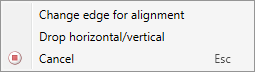
Change edge for alignment
Use this function to choose a different reference edge for alignment of the view. This function is only available for multiple cut edges.
Drop horizontal/vertical
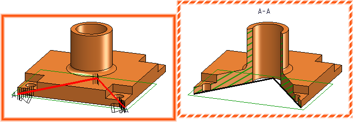
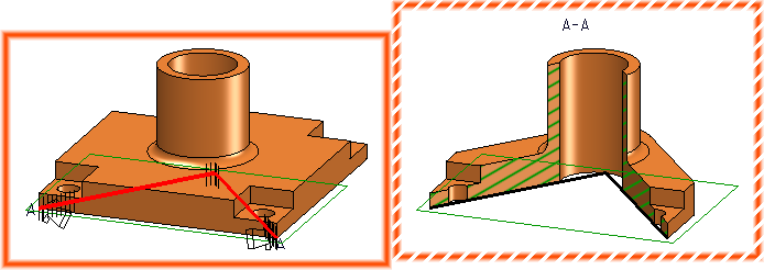
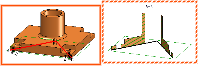
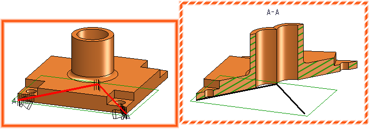
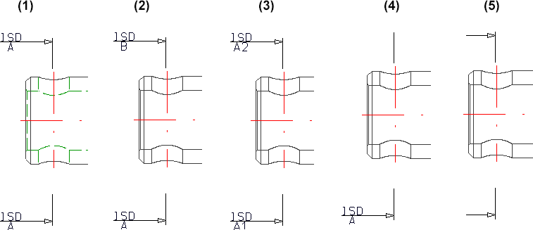
Use this function to drop the detail view horizontally or vertically. After calling the function you can select the rotation- upwards, downwards, to the left or right - with the cursor and drop the view. The viewing direction of the section will be determined in the moment of the function call, that is, it depends on the side of the reference edge on which you called the context menu with a right-click. The image below shows some different possibilities.
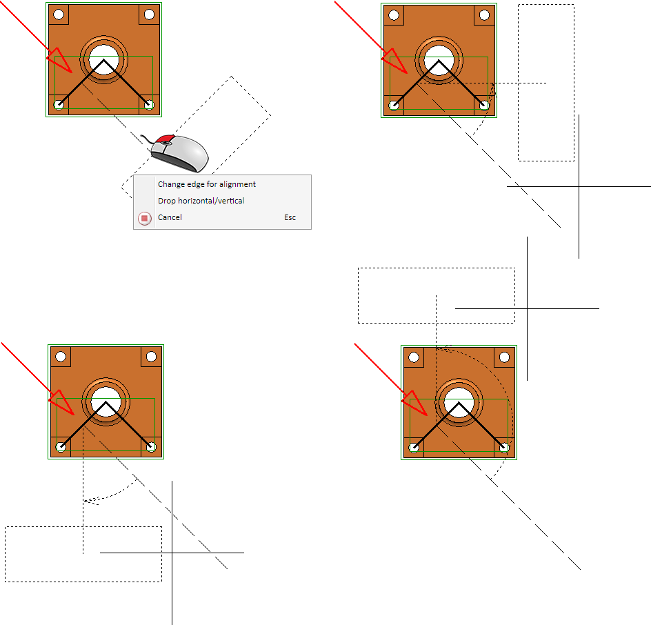
If the sectional view has been placed, it is marked in the preview with a dashed orange frame and the message The view has been places is displayed in the dialogue. If you want to correct the placement, click on .
The preview is only in cut form if the check mark is set on the preview button.
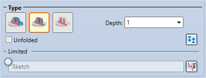
Type

|
Unlimited depth
|
|
|
Limited depth
|
|
|
Surface intersection
|


Click on  to reverse the viewing direction.
Ist zusätzlich die Checkbox  Unfolded checkbox is also active, all sectioned surfaces are unfolded into a common layer. This is useful, for example, if you want to display the inside of revolved solids, pipes, etc.
In addition, sectional views that are not opened can be limited laterally so that the section body does not completely penetrate the drawing. To do this, you must activate the Limited radio button.
If the option Limited is active, the current size of the section is displayed in the drawing as a rectangular sketch. The size of this rectangle is determined by the sketch and the height of the drawing or the parts to be sectioned.
Click on the  symbol to process the sketch, e.g.
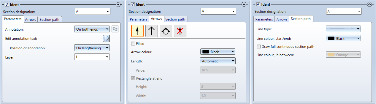
Identification of sectional views
Here you define the identification of the section in the original view and the sectional view. These are, among others, the symbolic representation of the viewing direction, content and position of the marking as well as the representation of the section course. If no identification is to be made, deactivate the checkbox Ident.
When this area is collapsed, the current marking is displayed next to the Ident checkbox.
You define the default settings for this area in the Configuration Editor under Drawing > Views > Ident.
Section designation
Here you define the section designation by direct input or selection from the list box.
If you have used uppercase letters or numbers in view markings in the sectional views of the drawing, HiCAD automatically suggests the smallest uppercase letter or the smallest number not yet used for the section designation. Views that only have a caption (without a designation in an original view) are also taken into account. Whether a letter or a number is suggested depends on the last designation used. For example, after a sectional view with the designation A, a letter is suggested again for the next section view, and after a section view with the designation 1, a number is suggested again.
|
Parameters |
|
|---|---|
|
Annotation |
This setting determines how the annotation should be done. The following settings are possible:
For Consecutive letters and Consecutive numbers, the direction can be reversed by activating the corresponding checkbox. For One-sided annotation, you can change the side. If Circle with triangle is selected as the symbol, only one-sided or double-sided annotation is possible. |
| Edit annotation text |
The ISD default setting for the annotation text is stored in the ViewOriginLabel_Section.ftd file in the HiCAD SYS directory. {Section designation (View marking)} If you want to change the default annotation text, click on |
| Position of annotation |
This setting determines the position of the annotation in relation to the section path. The following options are possible:
Left: position of the annotation in extension of arrow, Middle: on lengthening of section path, Right: beside arrow |
| Layer |
Here, you define on which layer the annotation should be stored. |
|
|
|
|
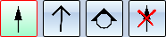
Arrows |
|
|
Here you determine which symbol is used for identification:
It is also possible to fill the closed arrow as well as the triangle. If you have selected the one-sided annotation, the Rectangle at end checkbox will be available for the Circle with triangle symbol. If the checkbox is active, a rectangle of the specified size will be drawn at the end point of the section path.
If the original view is a 3-D view, e.g. an axonometry, the selection of symbols will have no effect. In this case. a 3-D arrow will always be used. |
|
Arrow colour Length |
Here you select the colour and length of the arrows / symbols. The length can be determined automatically by HiCAD or explicitly by entering a value. |
|
Section path |
|
|
|
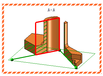
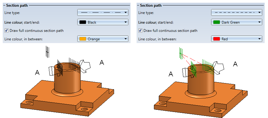
In this area of the dialogue window you determine the representation of the section path.
Different representations of the section path - here on a 3-D view
When calling this function for the first time within the current drawing, the settings from the Configuration Editor are used as default settings in the dialogue window (Drawing > Views > Ident > Sections). For further calls of the function, the last used text and line parameters are used as default. |
 . You can then define and format the text as in the
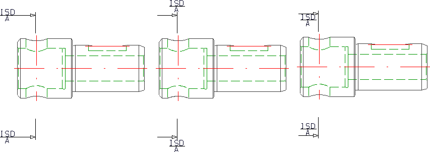
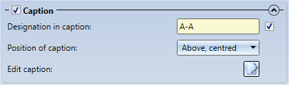
Caption
Here you can define the settings for the caption of the sectional view. To do this, you must first activate the Caption checkbox.
In the collapsed state, the current section designation is displayed next to the Caption checkbox.
|
Designation in caption |
Apply or change the view designation. |
|
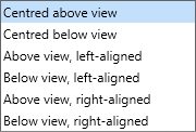
Position of caption |
Select the position of the caption - above or below the view, centred, left-aligned or right-aligned.
|
|
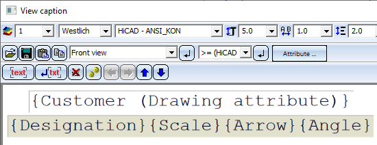
Edit caption |
If you do not want to use the ISD default settings for the caption of a sectional view, you can define individual captions by clicking on Determine the components that should be output in the caption. These can be fixed texts or attributes. For example, the view name, designation, scale and - if the view is not derived in alignment direction - arrow and angle can be transferred to the caption. For captions in sectional views, the template file VIEWHEADER_S.FTD is available in the HiCAD SYS directory. This file can be used to configure captions in sectional views individually. By default, the FTD file is empty at first.
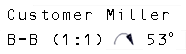
Example: For the template file VIEWER_S.FTD, the displayed setting was saved.
In consequence, the detail view will, for example, contain the displayed caption.
|
View properties
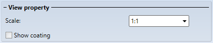
Here you can select the view scale.
For Sheet Metal parts and Steel Engineering plates you now have the option to specify whether the coating in the sectional view is to be shown or not, by activating or deactivating the Display checkbox beneath Coating in the dialogue window. The coating is displayed in the form of an offset edge, the so-called "coating line". The settings for the representation of the coating line can be found in the Configuration Editor at Drawing > Annotations > Coating line in sectional view.
The representation of the coating line can also be changed subsequently. To do this, right-click on the coating line in the required view and choose the desired function in the Coating symbol context menu:
|
Function |
|
|---|---|
|
|
Change coating line parameters Use this function to change the colour, line type and layer of the coating line. When you call the function, the 3-D edge parameters dialogue will be displayed for this purpose. |
|
|
Change offset distance Use this function to change the offset distance, i.e. the distance between coating line and cut edge. |
|
|
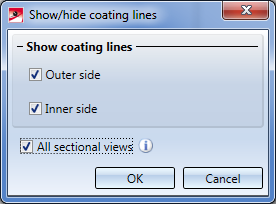
Show/hide coating lines Coating lines can be hidden or shown in the active view or in all sectional views. One distinguishes between coating lines on the inner side and the outer side. When you call the function, the following dialogue window will be displayed:
With the settings shown above, the coating lines will be shown in all sectional views on the outer side and inner side. If all coating lines have been hidden, the lines can be redisplayed again via the context menu for sheets: In the sectional view, right-click the sheet and choose Properties > Coating line. |


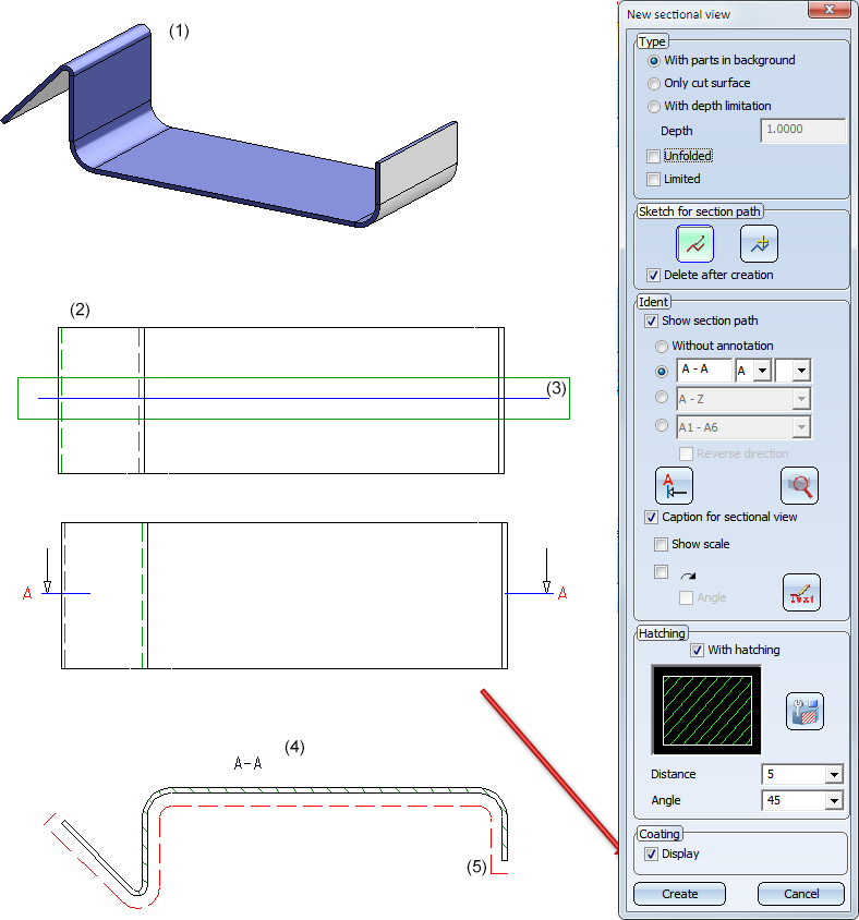
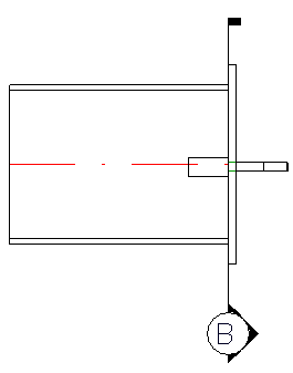
Sheet Metal part (1) with outside coating; Top view (2) with cut edge (3), Sectional view (4) with coating line (5)
Please note:
-
The offset calculation for the coating lines is always carried out in the screen plane, i.e. the lines are no "fixed", permanent 3-D polylines, but will be updated upon rotation of the view.
-
In dashed representations the dashing takes place segment-wise, but not over the entire length.
Hatching
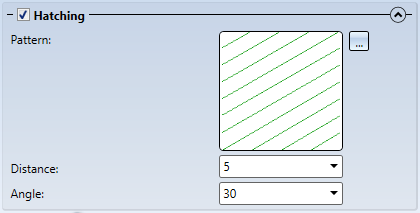
You can also display the section surfaces of a sectional view with hatchings.

To obtain a hatched display of the section surfaces, proceed as follows:
- Activate the With hatching checkbox. The current hatching setting is displayed.
- Select a different hatch pattern if necessary. Click on the Change hatching
 icon. The Hatch selection dialogue window is displayed. If you point the cursor on one of the patterns, more information about the hatch pattern is displayed. You can also zoom the display of the patterns by clicking on the magnifying glass symbol in the lower left corner.
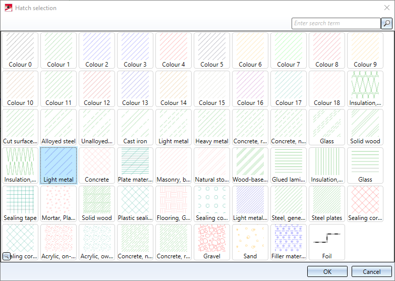
Select the desired pattern and confirm with OK.
- Specify the hatching line spacing and angle.
 The hatching of the cut surface is influenced by the setting that has been selected for the cut surface hatching parameter in the Configuration Editor at Drawing > Views. If the Cut surface hatching parameter is set to According to material, the hatching selection in the dialogues has no effect.
The buttons:
|
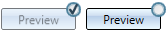
Preview |
If the check mark is set on the button, the preview is displayed automatically. Otherwise you must activate the preview by clicking on the button.
|
|
OK |
The sectional view is accepted and the dialogue window is closed. |
|
Cancel |
The dialogue is cancelled. A sectional view that has not yet been applied is not created. |
|
Apply |
The sectional view is taken over, the dialogue window remains open. You can directly create further sectional views. |
|
|
Some window areas can be opened/closed with |
|
|
The pin in the top right-hand corner can be used to set whether the original view should be retained after creating the section view or not. If |


 is displayed, an original view must be selected again after the sectional view has been applied.
Important notes
- A part's section behaviour, which is defined with the Cut, In sectional view + cut-out function determines whether it is taken into account in the sectional view.
- The sectional view created is automatically linked to the starting point.
- When the section surfaces are displayed, the settings of the Hatch section+cut-out function may possibly be used.
- Note also the Properties > Hatching functions in the context menu of the drawing. This function enables you to shade all section surfaces – irrespective of view - either according to material catalogue or by means of parallel lines.
- If you have generated the sectional view with a caption, it is automatically updated when the view is rotated.
- The representation of the section path and the identification of the section in the original view can be set in the Configuration Editor, at Drawing > Views > Ident > Sections. There, you can specify the position of the annotation (identification) at the section path and the line colour, line type and layer in the original view.
Please note that these settings do not apply to headings (captions).
- Sectional views, detail views or cut-outs that are not up to date are indicated in the ICN by strikethrough view names and by a red cross in the drawing. For example, this is the case if you are working with sectional or detail views or cut-outs and transform the model after definition of the views, or if you apply Boolean operations to the model.
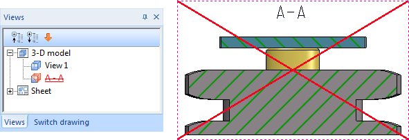
If you do not want the crossed-out representation in the drawing, you can change this in the Configuration Editor at System settings > Visualisation > Views, where you can deactivate the Cross out old cut outs, sectional views and detail views in graphic checkbox.
- l views, choose Views > Edit > Update
 .
. - The printer/plotter output of the drawing does not show the "red cross".
- If a parameterized sketch with the purpose Create/Edit is active in a sectional view, the line end points, isolated points and the degrees of freedom of the sketch are also visualized there.
Please note that the hatchings of cut surfaces will consider the hatching settings of the drawing. You define these settings with the function Drawing > Properties > Hatching settings.

Special Views (3-D) • Sectional and Detail Views (3-D) • Views (3-D)