Lettering
3-D Standard > Standard Processings > Bore >  Lettering
Use this function to apply letterings to parts. The letterings are placed into the active processing plane and are assigned to the active part.
First activate the part to which you want to apply the lettering. Call the Lettering function. If no processing plane has been chosen, HiCAD will prompt you to define one.
To enter the text for lettering, the text editor is displayed. Pre-set will be the last used settings here.
Enter the desired text for the lettering and select the desired text formatting. Alternatively, you can also re-use existing or pre-defined texts.
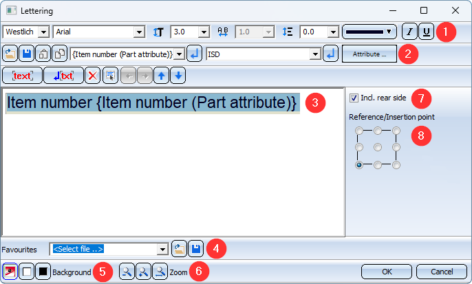
The options and functions of the dialogue window are as follows:
|
(1) |
Character set |
|
Text font HiCAD offers all installed HiCAD fonts and special HiCAD fonts for selection. There are proportional and non-proportional HiCAD fonts. The representation of the characters in the specified text height is scale-independent. The text height refers to the capital letters in standard text font. |
|
|
Font size |
|
|
Text width coefficient (only for HiCAD fonts) |
|
|
Line spacing |
|
|
Font colour |
|
|
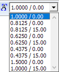
Typeface italic or underline (for Windows fonts only) When using HiCAD fonts, the aspect ratio and the inclination angle can be used instead to determine whether the text of the signature is italic or not. If a HiCAD font is selected, a corresponding selection box is displayed in the upper toolbar.
The box determines the typeface and the inclination of the text when using HiCAD fonts. If the aspect ratio is less than 1, the text is compressed. Similarly, with an aspect ratio greater than 1 the text is stretched. With an inclination of 0.00 degrees the text is displayed normally. With an inclination of 15.00 degrees the text is displayed in italics. |
|
|
(2) |
Load text from file Use this function to load ASCII files or formatted text (*.RTF, RichText). Text fonts of RTF files can be taken over, please note however that for 3-D texts only the first line of the file will be taken over. |
|
Save as text Use this function to save a text for later reuse - either as text file (.TXT, .DAT) or as comma-separated .CSV file. |
|
|
Paste from clipboard Use this function to paste the contents of the clipboard. If the clipboard contains a text which has been copied to it with the Text Editor, the complete HiCAD text formatting (colour, font, height, italic, bold, line spacing etc.) will be taken over. If texts are taken from other Windows applications the font can be taken over if desired, but not the colour or height. |
|
|
Copy to clipboard The currently selected text is copied to the clipboard. If the contents of the clipboard are pasted to other Windows applications, HiCAD fonts are taken over as Courier font. |
|
|
History / Predefined texts Previously used texts as well as predefined ISD texts can be taken from the list box: Select the required text in the list box and click the |
|
|
Attribute Attributes can be easily copied from the list box. Select the attribute and click OK. Restrictions:
|
|
|
(3) |
Generated text |
|
(4) |
Favourites Letterings can be saved as favourites. The file format is *.FTD. In the HiCAD SYS directory you will find various FTD files with predefined lettering. |
|
(5) |
Background Use these buttons to temporarily change the background of the text input area. This is useful if the selected colour is difficult to read on the current background. |
|
(6) |
Zoom Use the Zoom functions to enlarge or downsize the text shown in the input area. |
|
(7) |
Incl. rear side If you want the lettering to also appear on the back side of the part, activate the Incl. rear side checkbox. |
|
(8) |
Reference / Insertion point The text can be placed in nine different positions relative to its reference point. You select the desired position by activating the corresponding radio button. |
 icon.
icon. If you want to apply the lettering as shown in the dialogue window, exit the window with OK. Use the HiCAD point options to specify the insertion position of the lettering. If you want to rotate the lettering or change its direction before insertion, right-click and select the required function from the context menu.
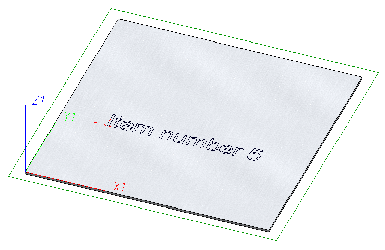
Part with lettering, also on back of part
Letterings can be inserted several times, i.e. the function remains active after insertion of one lettering, and HiCAD prompts you to specify the insertion position of the next lettering. Furthermore, you have the option to activate a context menu with a right-click. You can then rotate the lettering, change its insertion direction, activate another part or select another lettering.
You end the Lettering function by pressing the middle mouse button or selecting Cancel in the context menu.
Updating
The lettering can be updated without feature recalculation. The lettering text can contain attributes such as the item number. If this changes, the lettering must be updated without changing the part in any other way. No feature recalculation is allowed. Otherwise, the item number would be invalidated because geometric changes cannot be excluded. An update generates the complete text as lettering lines. The lettering lines lie in one plane.
-
Automatic update: Lettering texts that use attributes are automatically updated when the attributes (e.g. the item numbers with the Itemise part function) are changed.
-
Manually: To do this, right-click on the Lettering feature and select Update lettering. All lettering texts of the part are updated without feature recalculation.
Letterings during modelling
Due to the possibility of updating, letterings must be specially taken into account when modelling. The update cannot know whether a lettering has been trimmed or deformed, for example. The lettering should look the same after modelling as it does after updating. That is, it is processed completely or not at all.
If the lettering has been changed, e.g. deformed, the update is deactivated, as the update would create the lettering lines in a different position. The lettering can then only be created again by the feature recalculation.
![]() Please note:
Please note:
- The lettering is entered into the feature log of the part. To change the text, double-click the Number punches entry.
- The lettering can be shown or hidden in the view. To do this, right-click on the view frame and select the function Show/hide elements in view.
-
The Lettering function can also be found in the context menu for general 3-D parts (3-D).
Surface types for lettering
-
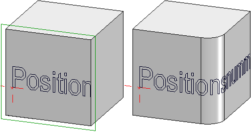
For Extruded parts, the lettering is placed on the surface defined by the processing plane. If the surface has a tangential transition, the lettering is continued to the next edge. The same applies to solid primitives of the cuboid, prism, pyramid and tetrahedron type.
-
Lettering can be created either on the lateral surface or the circular surfaces of the solid primitive Cylinder and the revolved part. The lettering cannot be continued beyond the edge or fillet.
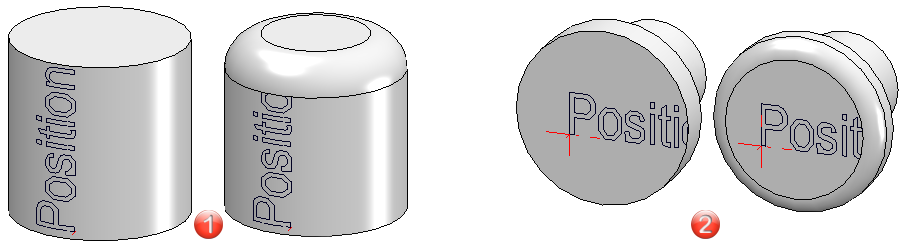
(1) Solid primitive cylinder
(2) Revolved part -
The lettering is continued on edge plates via the tabs and bend zones. You can also insert the lettering in the bending simulation.

(1) Bending simulation
(2) Sheet with finished bending simulation -
No lettering can be created on the solid primitives cone, sphere and torus.


Standard Processings (3-D) • Repeated Fitting of Standard Parts (3-D)