Show/Hide Elements

Especially when displaying polyhedrons and freeform surfaces, certain edges that conflict with the rules of technical drawing need to be hidden. Edges are therefore assigned an internal ID, which identifies them as a normal or tangential edge, mesh edge in m-direction, n-direction, mesh diagonal or polyhedral lateral edge. Here, m and n are the natural parameter directions of a surface, e.g. latitude and longitude of a sphere.
Furthermore, this function enables you to show and hide assembly points, isolated points, weld seams, processing planes, lettering and cut edges in the active view.
The dialogue window
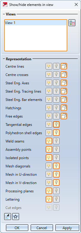
The selected views are listed in the upper part of the dialogue window. After calling up the function, this is initially the active view or the current view list.
To select further views, simply click on the corresponding view frame in the drawing. If the frame of an already selected view is clicked again, the view is removed from the list. Alternatively, views can also be removed from the list by right-clicking on the corresponding entry in the list and then selecting the Remove element(s) from list function.
For the various elements, you can then select whether they are to be
 shown,
 hidden or
 covered in HiddenLine mode.
The selected setting is always indicated by an orange frame.
|
|
Switch to view selection |
|
|
The current settings can be saved as favourites and used again at any time. They are saved in the ProgramData\ISD Software und Systeme\HiCAD 2024\Favourites\VisGUI\ShowAndHideElements folder. You can find out more about favourites management here. |
|
|
This function can be used to adopt the settings of another view. To do this, select the corresponding view in the drawing. |
|
OK |
The current settings are applied to the selected views and the function is cancelled. |
|
Apply |
The function is cancelled without changing the views. |
|
Cancel |
The current settings are applied to the selected views. The view list in the dialogue window is emptied and the dialogue remains open. |


Please note the following when making multiple selections of views (view lists):
If the settings of the views contained in the list differ, this is indicated in the dialogue of the function by a blue border around the corresponding setting.
Example:
The drawing contains a top view in which the centre lines are hidden and an axonometric view in which they are displayed. If you now select both views and call the Show/Hide elements in view function, the row Centre lines is outlined in blue and the text Different values appears on the info button.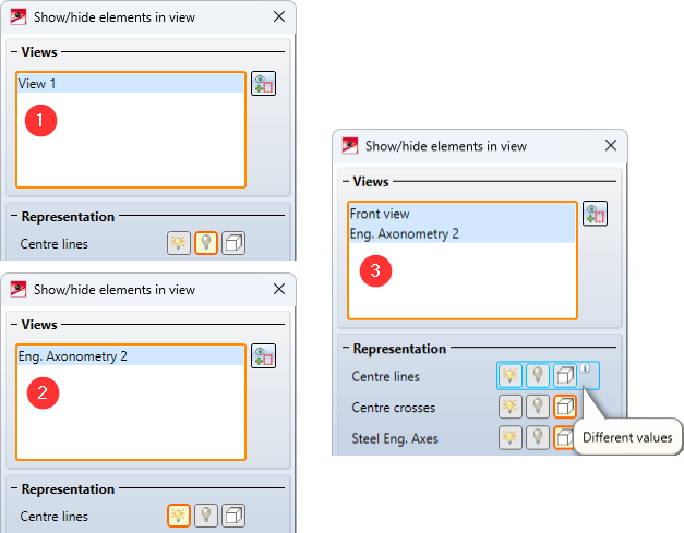
 The function is also available in the context menu of views and view lists.

Edge type
To be able to show/hide specific edges or to display them hidden, you need to know which Edge ID exists or can exist in which part type:
|
Edge type |
Possible Representation |
|
|---|---|---|
|
Centre lines Centre crosses |
Crosshairs and surface axes of various 3-D elements |
|
|
Steel Eng. Axes, Tracing lines, Bar elements |
Steel Engineering beams and profiles, Bar elements etc. |
|
|
Free edges |
Edges that do not attach to a surface and are not part of a composite edge. Free edges can, for example, represent a symmetry axis in solid bodies. Thread edges are handled like free edges. |
|
|
Hatchings |
If you do not want hatchings to be displayed, deactivate this option. This setting applies to both 3-D surface hatchings and hatchings of sectional views, details and cut-outs. If the option is active, you can hide hatchings that would not normally be visible. Such cases can, for example, occur with sectional views. |
|
|
Tangential edges |
Edges the adjacent surfaces of which form an angle of 0 degrees. |
|
|
Polyhedron shell edges |
Cylinder, cone (as polyhedron model) Fillets (depending on generation) |
|
|
Weld seams |
Symbolic weld seam edges (has no effect on weld seams created with HiCAD versions before Version 2017) |
|
|
Assembly points |
Assembly points (automatically or manually set points)
|
|
|
Isolated points |
Isolated points- also named points, symbol points and fitting points
|
|
|
Mesh diagonals |
Sphere, Torus: Latitudes (U-direction), longitudes (V-direction) 3-D revolved part, cross-section (V-direction), lines between cross-sections (U-direction) Fillets (depending on generation) |
|
|
Processing planes |
Processing planes - no sketch planes |
|
|
Lettering |
Lettering - for marking or numbering parts |
|
|
Cut edges |
If the view is a sectional view, detail view or a cut-out, you can specify here whether the edges between the section surfaces should be shown/hidden. |
|
The Hidesetting only affects the Glass Model representation.
Examples:
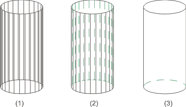
(1) Glass model, (2) Hidden
line with lateral edges, (3) Hidden line without lateral edges
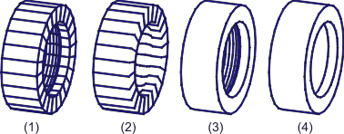
(1) All edges visible, (2) Without mesh edges in v-direction, (3) Without mesh edges in u-direction, (4) 30 degree limiting angle
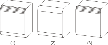
(1) All edges on, (2) Polyhedral lateral edges off, (3) Tangential edges off
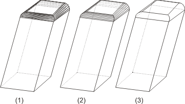
(1) All edges on, (2) Mesh diagonal off, (3) Mesh in v-direction + mesh diagonal off
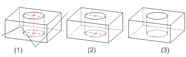
(1) Cuboid with free edges, centre lines and crosshairs, (2) Free edges + centre line off, (3) Free edges + centre line + crosshairs off
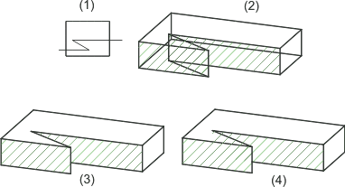
(1) Top view with sketch for the section path, (2) Glass model with hatching, (3) Overlap hatching for a hidden line, (3) Do not overlap hatching for a hidden line
![]() Please note:
Please note:
- For assembly points and isolated points, hiding always affects only the existing points. This means that if further isolated points or assembly points are created, these will be visible. You must first recalculate the view in which the isolated points and assembly points are already set to Hide. To do this, use the functions found under Recalculate views in the context menu of the Redraw function.
- Clicking
 opens a menu with further edge representation functions:

defines colour and line type of hidden edges.

highlights edges in colour in Glass Model or HiddenLine representation.
In addition, the Show/Hide edges function can be used to show/hide any edges of a part in Glass Model and HiddenLine representation.
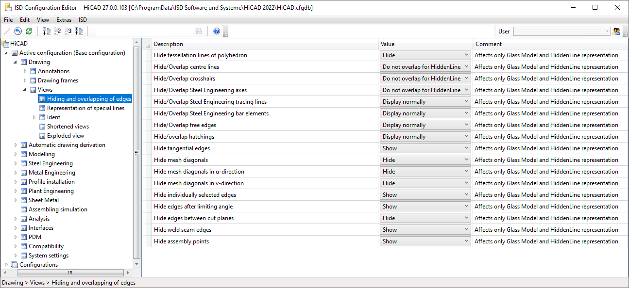
- The presettings for this dialogue window can be changed in the Configuration Editor, at Drawing > Views > Hiding and overlapping of edges.