Steel Engineering - What's New

Service Pack 2 2023 (V 2802)
Insert new beam
The function for inserting beams and profiles has been redesigned and significantly expanded with SP2. With the new Insert new beam  function, not only 3-D standard beams and profiles but also multi-part standard beams, prototype beams and elongated plates can now be inserted. The selection is made in the following catalogues:
- Semi-finished products > Plates,
- Semi-finished products > Cold rolled sections,
- Semi-finished products > Beams + Profiles,
- Factory standards > Multi-part standard beams and
- Factory standards > Prototype beams.
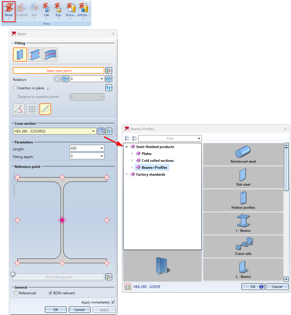
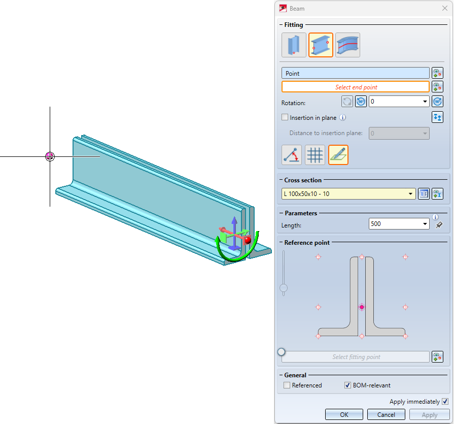
Once you have now entered the required parameters, a preview of the beam is displayed. Another new feature is that a fitting point can now be selected to simplify insertion.
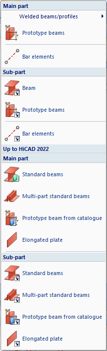
The previous functions for beam insertion (before HiCAD 2023), which are now integrated into the new functionality, are still available in the menu under Up to HiCAD 2022.
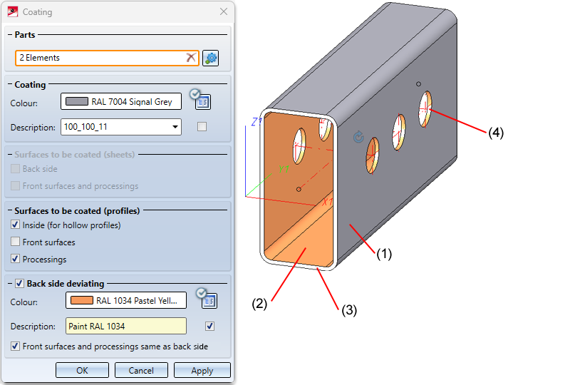
Coat beams and profiles
In addition to sheets and plates, as well as general 3-D parts, beams and profiles can now be processed with the Coating  function.
You can find the function at Steel Engineering > Further functions > Coating.
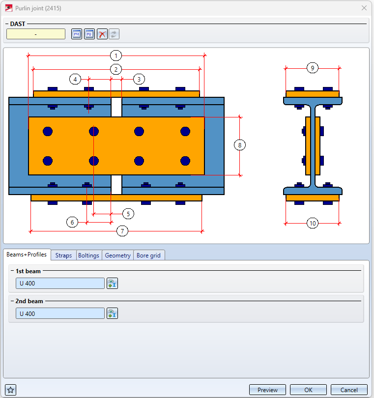
Purlin joint according to DAST PM/PQ (2415)
The previous design variants for purlin joints,
- Purlin joint acc. to DAST PM (405) and
- Purlin joint acc. to DAST PQ (415)
have been replaced with SP2 by the new Design Variant Purlin joint acc. to DAST PM/PQ (2415). This variant connects two beams by beams of a rigid joint. Allowed are I- and U-beams, which have to be aligned accordingly. The insertion can be carried out can be user-defined or - with corresponding beams - based on a table according to DAST PM or PQ.
In the user-defined configuration, the joint can be created with one strap each on the upper and lower flange as well as on the web, whereby all straps as well as the corresponding boltings and hole patterns can be set separately. U-beams or flat steels are possible as straps. The connection can be created flush or with clearance.
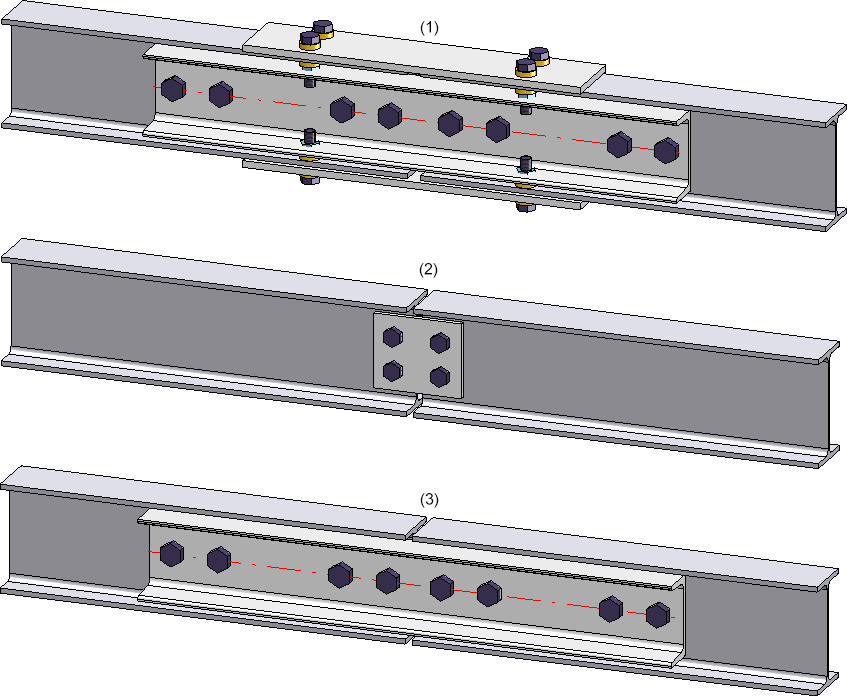
(1) User-defined, (2) DAST PQ, (3) DAST PM
Automatic dimension calculation for beams and plates
Beams
If the automatic dimension calculation is active in configuration management, the calculation for beams can now be restricted so that only the length is determined by the automatic dimension calculation and any values for width and height transferred from the catalogue are retained.
Plates
If the automatic dimension calculation is activated in the Configuration Editor, length, height and width are calculated and assigned to the attributes Length ($03), Width ($02) and Height ($04). Length and width are sorted. That is, the largest value is assigned to the length..
You can find more about the automatic dimension calculation here.
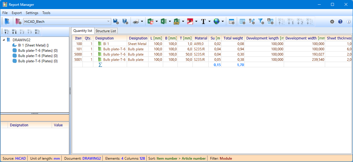
Steel Engineering plates - Development length and Development width
For Steel Engineering plates, the Length, Width and Height are now additionally assigned to the attributes
- Development length (§L2D),
- Development width (§B2D) and
- Sheet thickness (§T2D)
In this way, uniform bills of materials can be created for Sheet Metal parts and Steel Engineering plates..
Unlike Sheet Metal parts, the values are calculated automatically, i.e. the settings for Sheet Metal parts in the Configuration Editor at Modelling > Part properties do not apply to Steel Engineering plates!
For drawings saved before HiCAD 2023 SP2 (V 2802), a feature recalculation must be performed in order for the values to be calculated.
Laminated glass
Laminated glass - Definition of the article number
For the individual layer structure of laminated glass, various options are now available for defining the article number:
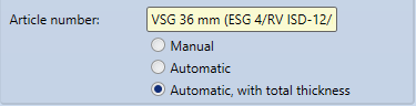
- Manual
The article number can be assigned as desired. - Automatic
The article number is automatically generated based on the layer structure by combining the designations of the individual layers separated by a separator. The default separator is "/". However, this can be changed in the Configuration Editor at Steel Engineering > Products > Laminated glass pane > Separator for auto-generated article number of a laminated glass pane.
Example: ESG 8/RV ISD-08/ESG 6 - Automatic, with total thickness
Here, too, the article number is generated according to the layer structure as with the option Automatic, but here the total thickness is also output.
Example: VSG 16,2 mm (ESG 8/Folie 0.2/TVG 8)
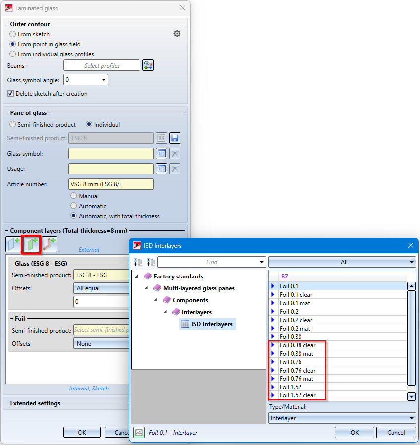
Additional layer thicknesses
From SP2 onwards, the Laminated glass  function makes additional film thicknesses available when installing individual glass panes with foil layers - 0.38, 0.76 and 1.52, each in matt and clear version.
Changed default setting for beam and profile representation
The default setting for the type of beam and profile representation has changed. Beams and profiles are represented exactly by default from SP2 onwards. The default setting can be changed in the Configuration Editor at Steel Engineering > Representation > Type of beam representation. The changed default applies to new installations only.
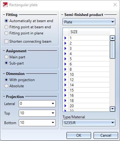
Rectangular plate - New function
For the insertion of rectangular plates the new function Rectangular plate  is now available at Steel Engineering > Plate, new. The previous function Standard has been moved to the sub-menu.
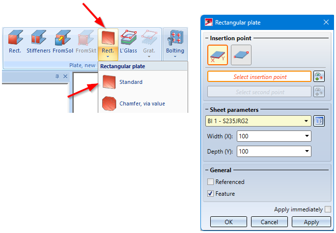
The new function can be used to install plates from the HiCAD catalogue Semi-finished products > Plates. The function basically corresponds to the Sheet Metal function Create base sheet.
- Semi-finished product selection,
- Insertion via points or value input,
- Referenced saving,
- Feature creation,
- Integrated preview function.
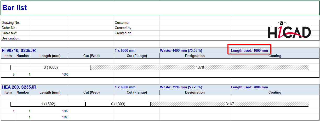
Enhanced bar list
As of SP2, the Excel bar list displays not only the waste but also the actual length used. The BOM template for Steel Engineering has been adapted accordingly. (see also: Report Manager - What's new?).
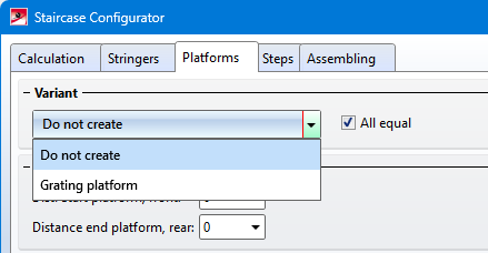
Enhanced Staircase Configurator
-
Stairs can now also be created without platforms. For this purpose, the new variant Do not create is available on the Platforms tab.
-
If Standardized grating step is selected as the variant on the Steps tab, the direction of the bolted connection can now be reversed. To do this, activate the new Bolts from inside checkbox.
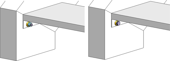
Left: Bolts from outside, Right: Bolts from inside
Gratings - Dimension calculations
In the dimension calculation, the bearing bar direction of gratings is assigned to the attribute Length ($03). The bearing bar direction is ignored in the dimension calculation if the direction is set manually for the grating. This concerns the following cases:
- The dimension orientation is set.
- The part orientation is set.
- The processing direction is set.
The bearing bar direction is also taken into account for the part and dimension orientation.
|
|
The part orientation results from the bearing bar direction (only for Grating steps DIN 24537). |

|
The part orientation results from the bearing bar direction of the assembly main part (only for Gratings steps DIN 24537). |
|
|
The dimensions are up to date, the dimension orientation results from the bearing bar direction (only for Gratings steps DIN 24537). |
|
|
The dimensions are up to date, the dimension orientation results from the bearing bar direction of the assembly main part (only for Grating steps DIN 24537). |


Unbend beams and profiles
Multi-part beams and profiles consisting of straight and circular curved sections can also be unbent. However, the sections must merge tangentially.
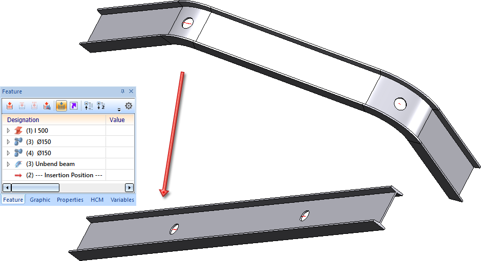
With HiCAD 2023 SP2 (V 2802) the geometric algorithm of the unbending calculation has changed. Therefore, there may be changes in the result. In particular, beams, which could also be unbent before, lie differently in space (see image). However, beams already unbent with a version before HiCAD 2023 SP2 will not be changed.
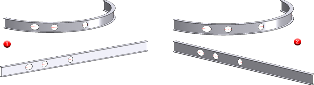
(1) Unbending with HiCAD 2022, (2) Unbending with HiCAD 2023 SP2
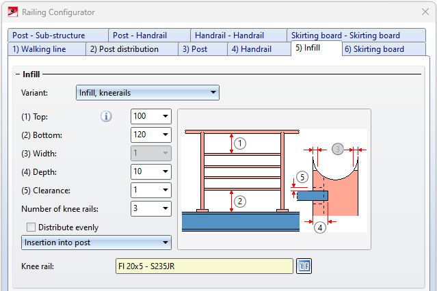
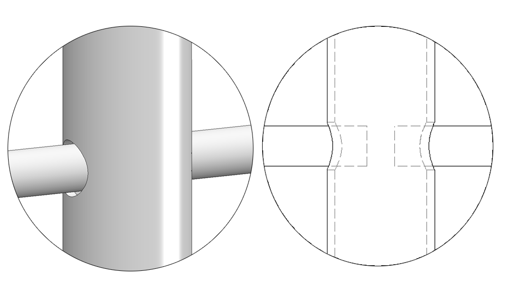
Railing Configurator - New variant for knee rails
Knee rails of a railing can now also be inserted into the post. For this purpose, the new variant Insertion into post is available on the Infill tab for infills with knee rails.
Service Pack 1 2023 (V 2801)
Railing Configurator - new base plate types
In the Railing Configurator, new base plate types are available on the Post - Sub-structure tab:
- One-sided, no bore,
- One-sided, 1 bore,
- One-sided, 2 bores in transverse direction
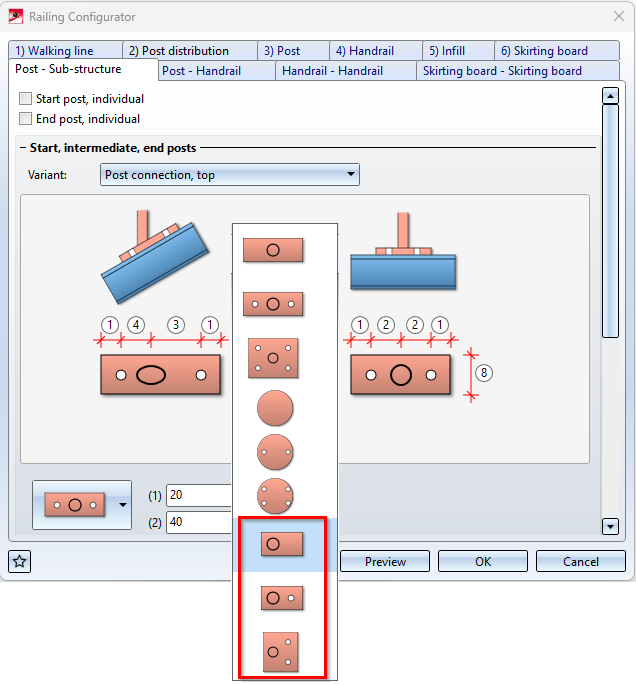
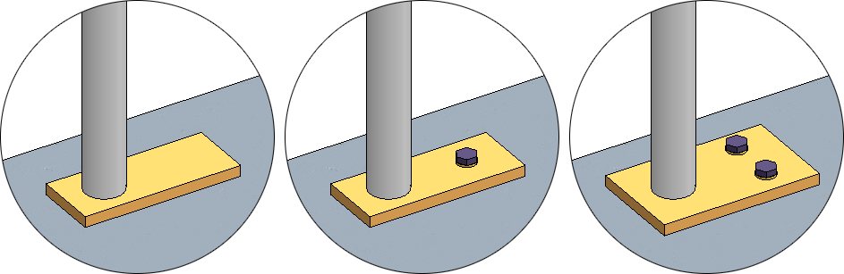
(1) One-sided, no bore; (2) One-sided, 1 bore; (3) One-sided, 2 bores in transverse direction
Purlin joints 3204 and 3206
The Purlin joints 1204 and 1206 have been modernised and adapted to the HiCAD standard. In this context, the joint numbers have been changed to 3204 and 3206.
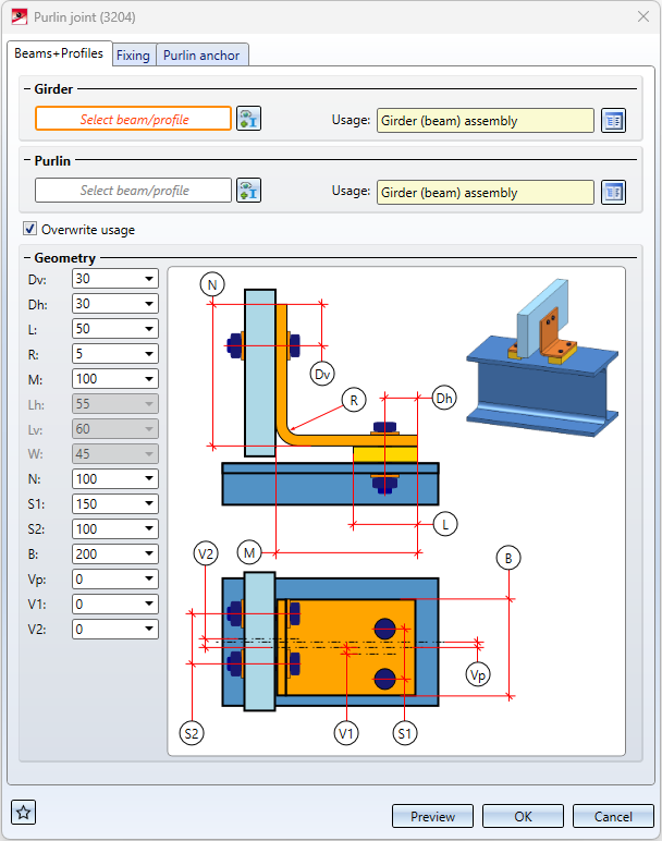
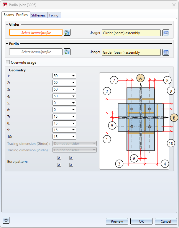
For example, the current settings are now visualised in the model drawing during input, e.g. the insertion direction, stiffeners and boltings.
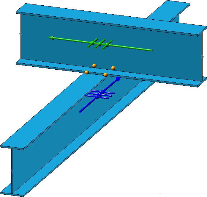
In addition, there are now - compared to the previous purlin joints - more setting options available. Examples are the offset of the purlin to the beam and the usages for the assemblies, etc.
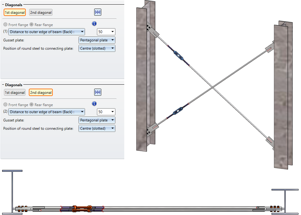
Cross-bracings 2601 / 2602 - Distance of the gusset plates from the flange
From HiCAD 2023 SP1 onwards, Cross-bracings 2601 and 2602 can also be installed with indication of the distance of the gusset plates from the front or back flange. This is used, for example, in hall construction. There it can happen that a cross-bracing is to be installed between two differently sized beams whose upper flanges are on the same level.
For this purpose, the Fixing tab has been extended accordingly.
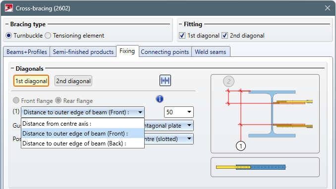
In this case, however, the gusset plates cannot be fixed to the flange, i.e. the corresponding checkbox on the Connecting points tab must not be active.
Example:
The Cross-bracing 2601 shown was selected with the following settings for the 1st and 2nd diagonal:
Major Release 2023 (V 2800)
Dialogue windows for connections
Opening the dialogues of Steel Engineering connections and scrolling through the dialogues has been accelerated.
Circumferential seams for stiffeners
For stiffeners, circumferential seams are often used in practice, which also makes drawing in particular much easier. For this reason, the corresponding tabs of the following design variants have been extended:
|
Design variant |
Tab |
|---|---|
|
Stiffener (2401) |
|
|
Strap joint (2310) |
|
|
Beam to web, with 2 plates + stiffener (1211) |
|
|
Column connection, Frame corner (2203) |
|
|
Column connection, Frame corner (2204) |
|
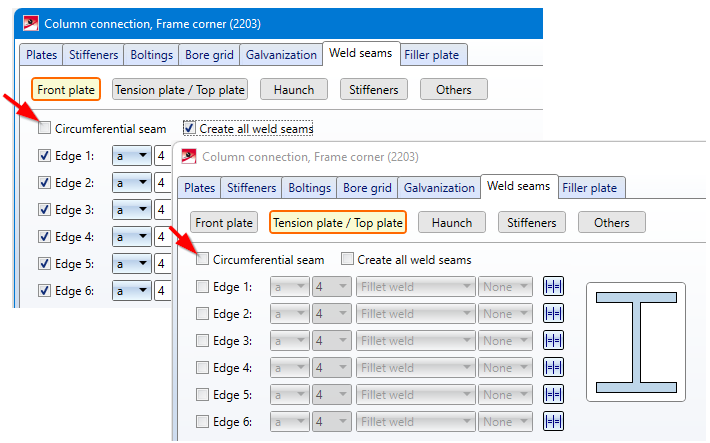
 Please note that circumferential seams cannot be applied to haunches and ribs.
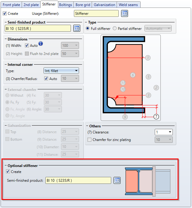
Beam to web, with 2 plates and stiffener - Optional 2nd stiffener
With the Beam to web, with 2 plates and stiffener (1211) connection, a second stiffener can now be optionally installed - aligned with the first stiffener.
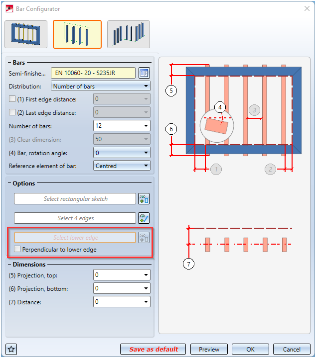
Bar Configurator - Bars on free sketch
With the Bar Configurator, the area between the edges of a "free" sketch can now also be filled with bars. Until now, only square sketches were allowed here.
After selecting the sketch, you determine the lower edge of the installation area and then the direction of the installation or you select the installation perpendicular to the lower edge.
The installation of the bars is always determined by the sketch line defined as the Bottom (see A in the example), so the entire sketch is not necessarily filled with bars.
Example
The area between the six edges of the sketch shown is to be filled with bars..
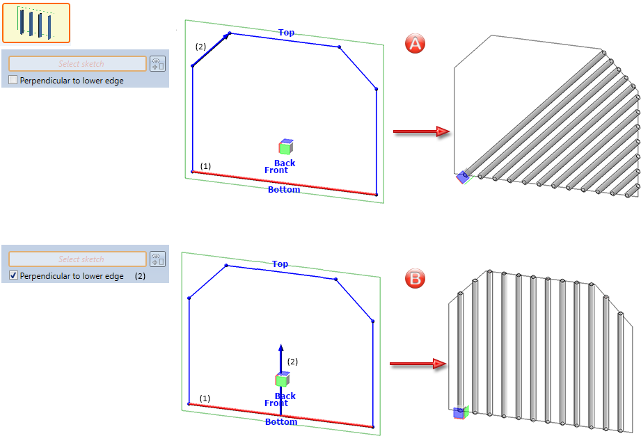
A: (1) lower edge, (2) direction / B: (1) lower edge, (2) perpendicular to lower edge
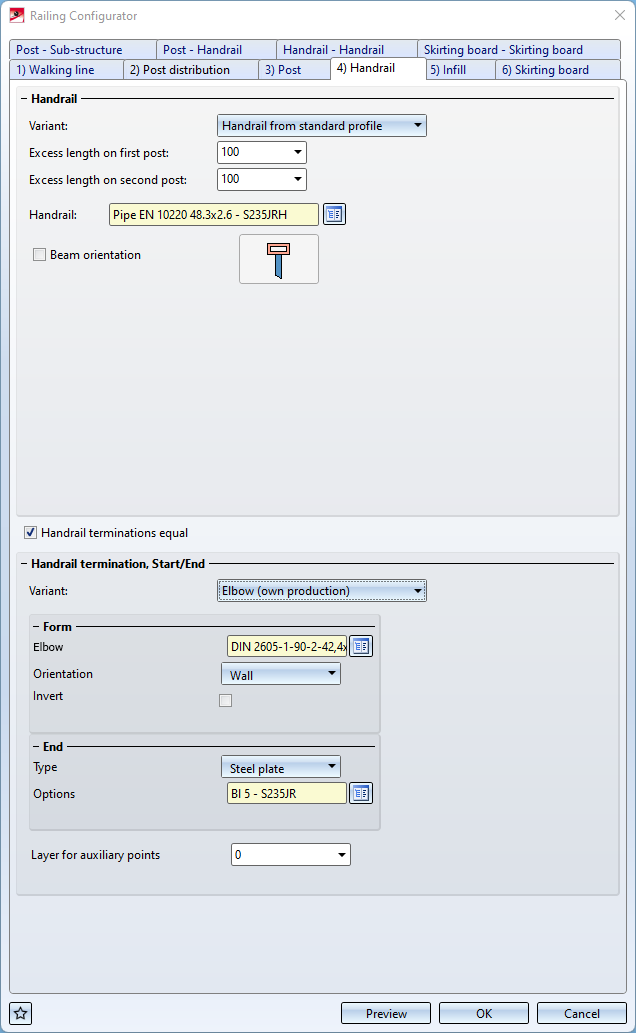
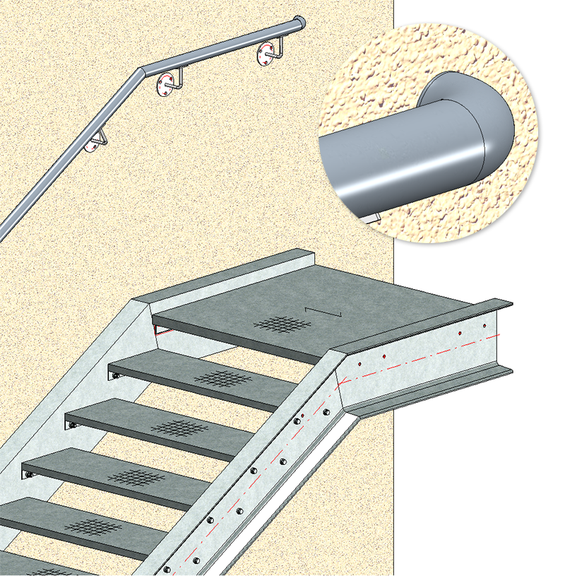
Railing Configurator - Elbow at hand rail end
On the Handrail tab of the Railing Configurator, elbows with/without end cap or steel plates can now be placed at handrail terminations.
3-D grid
As with the 3-D function of the same name, the dialogue window of the 3-D grid function has been revised and modernised.
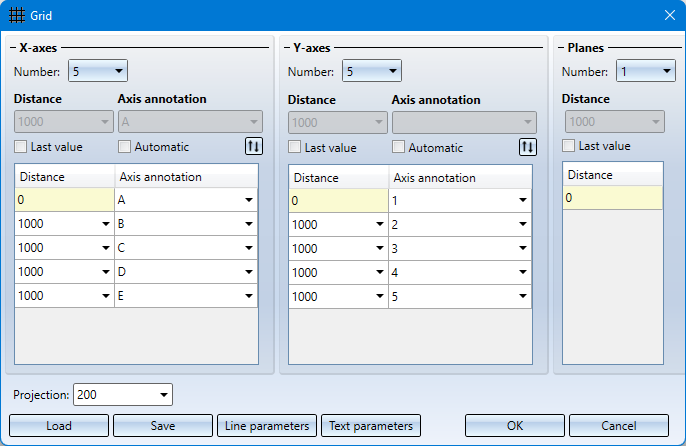
Also new is that you can use formulas instead of values for the distance specification - also in mixed units. The value is then converted into the unit of measurement of the model drawing.
Example:
Unit of measurement of drawing: mm, Distance: 1 3/4" + 12.5 mm. Result: 56.5 (mm).
Rectangular plates - Revised dialogue
The dialogue window of the function Rectangular plates  has been revised and modernised.
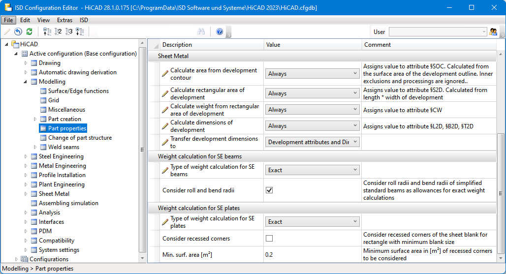
Settings for weight calculation
In the Configuration Editor, the settings for weight calculation have been moved. You can now find the parameters at Modelling > Part properties.