Plates
Steel Engineering > Plate, new
HiCAD enables you to insert all kinds of plates or plate-like parts as attached parts in Steel Engineering constructions.
The following functions can be found in the Plate, new function group:
|
|
Insertion of rectangular steel engineering plates, e.g. front plates for beams. | |
|
|
Stiffeners with corner, chamfered or filleted (internally or externally), one-sided or two-sided, as partial stiffeners or full stiffeners. |
|
|
|
Converts a 3-D solid into a plate part. | |
|
|
Derives a plate from a sketch. | |
|
|
Rectangular plate |
Inserts a rectangular plate from the HiCAD catalogue Semi-finished products > Plates. Other plates can be found in the pull-down menu |
|
|
Insertion of glass panes from sketches. |
|
|
|
Insertion of grating steps. |


 , e.g. further rectangular plates, gusset plates, trapezoidal plates etc.

![]() Please note:
Please note:
- If you select
 > Settings > Basic settings > General > Parametric dimensions: Yes, the plates are fitted with their parametric dimensions. You can then change
the plate size quickly and easily by changing the relevant parametric
dimensions. To do this, right-click the relevant parametric dimensions and choose
the Parametric dimensions function in the context menu.
Enter the new value and click OK to exit the input
window. The plate is updated immediately.
> Settings > Basic settings > General > Parametric dimensions: Yes, the plates are fitted with their parametric dimensions. You can then change
the plate size quickly and easily by changing the relevant parametric
dimensions. To do this, right-click the relevant parametric dimensions and choose
the Parametric dimensions function in the context menu.
Enter the new value and click OK to exit the input
window. The plate is updated immediately. - When fitting catalogue standard parts and semi-finished products (Steel Eng. beams/profiles, plates) in HiCAD, values from the catalogue item are assigned to some part attributes of the HiCAD part (e.g. the "Attribute number" part attribute is assigned to the "BZ" column). This configuration is freely configurable.
In the catalogue tables you have the option to link a table column to a part attribute. When fitting a part from this table in HiCAD, the value of the linked column will then be assigned to the part. A user can, for instance, enter the article number and/or the supplier in a column, and the value will be assigned to a part attribute when fitting a part and can subsequently be used for part annotations or bills of materials. In the catalogue table (see Catalogue Editor) linked columns are identified by a link symbol in the column header. From version 2008 onwards, the "BZ" columns of tables for standard parts and semi-finished product are linked to the part attribute "$BB"; "CUSTOM1" columns are linked to the part attribute "CUSTOM1", and "CUSTOM2" columns are linked to the part attribute "CUSTOM2". - The processing direction is taken into account when calculating the length and width of Steel Engineering plates.
Example:
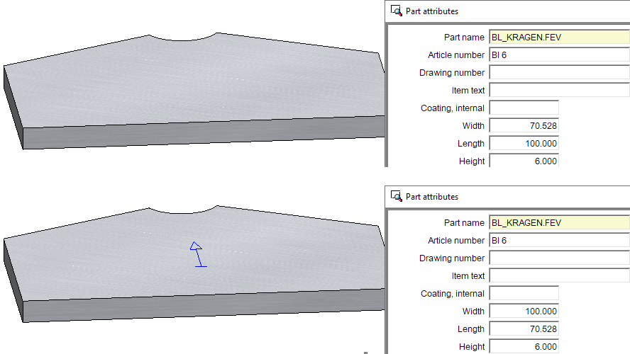
-
For Steel Engineering plates, the Length, Width and Height are now additionally assigned to the attributes
- Development length (§L2D),
- Development width (§B2D) and
- Sheet thickness (§T2D)
In this way, uniform bills of materials can be created for Sheet Metal parts and Steel Engineering plates..
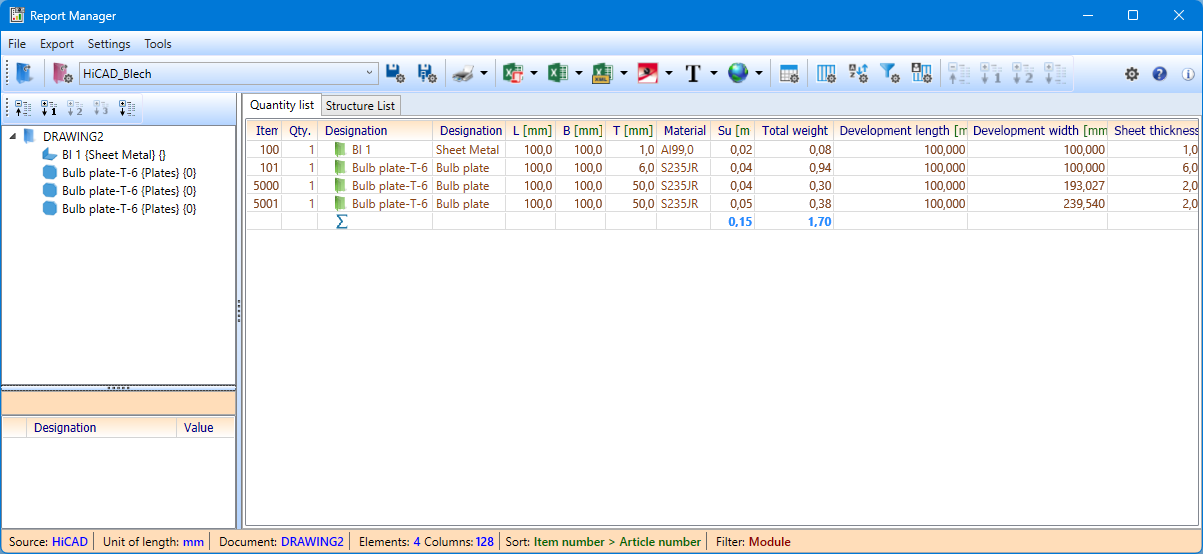
Unlike Sheet Metal parts, the values are calculated automatically, i.e. the settings for Sheet Metal parts in the Configuration Editor at Modelling > Part properties do not apply to Steel Engineering plates!
For drawings saved before HiCAD 2023 SP2 (V 2802), a feature recalculation must be performed in order for the values to be calculated.
Please also read the notes on automatic dimension calculation.

