Rectangular Plates and Other Plates
Steel Engineering > Plate, new > Rectangular plate 
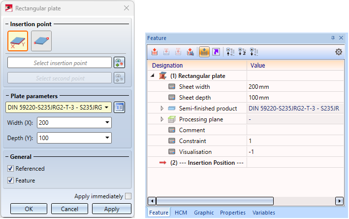
Rectangular plate
With this function you insert a rectangular plate from the HiCAD catalogue Semi-finished products > Plates. Click on  to open a pull-down menus with functions for other plates.
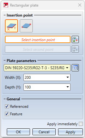
Insertion point and Plate parameters
The width and depth of the plate can be determined either by selecting two points or by entering values. Plate thickness and material are determined by catalogue selection.
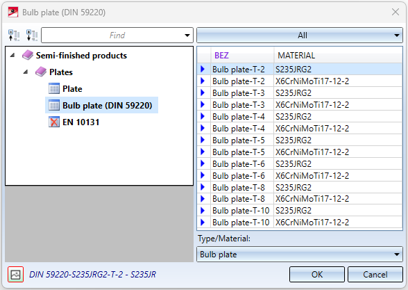
Click on  , select the desired plate in the catalogue and then clickOK.
Under Insertion point, activate the desired insertion mode.
|
|
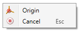
Insertion via points First determine the insertion point of the plate, i.e. the position of the plate in the drawing. Then you can draw the plate dynamically with the cursor. The selection of the second point determines the width and depth of the plate. These values are displayed under Plate parameters, but cannot be changed here. A subsequent change is possible via the plate feature - if available. When selecting the insertion points, a context menu can be activated with the right mouse button. Here the Origin of the drawing can also be selected as insertion point
|
|
|
Insertion via value Enter the Width and Depth of the plate under Plate parameters. A preview of the plate is displayed. Now select the insertion point, i.e. the position of the plate in the drawing. |


If the Apply immediately checkbox is active, the new plate is installed immediately if it makes sense to enter it and can then be changed later using the Plate feature, if available.
If the checkbox is inactive, a preview of the plate is displayed first. The parameters can then still be changed, for example, the insertion points can be changed after clicking on  . Only after a click on the Apply button (or on OK or by pressing the middle mouse button) will the plate be inserted.
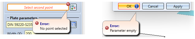
Incorrect or missing entries are indicated in the dialogue by the  symbol or the
  symbol on the OK button. If you move the cursor over the symbol, a corresponding message is displayed, e.g.:
General settings
|
Referenced |
If the plate is to be referenced, activate this checkbox. In this case, the Reference, Save dialogue is displayed after the plate has been accepted. |
|
Feature |
Activate this checkbox if a feature of the plate is to be created. The entire creation process of the plate is then recorded in a feature log and can be changed later.
|
Buttons
|
OK |
The plate is inserted as shown in the preview. The dialogue window is then closed. |
|
Apply |
The plate is inserted as shown in the preview, but the dialogue window remains open. You can then directly insert further plates without calling the function again. |
|
Cancel |
The dialogue window is closed without inserting the plate. |

Other plates
Steel Engineering > Plate, new > Rect. 
Clicking opens a pull-down menu with other functions for other plates:
|
|
Rectangular plate: Chamfer via value |
(1) Chamfered plate, (2) Internally filleted plate, (3) Oblique-angled plate, (4) Filleted trapezoidal plate, (5) Collar plate, (6) Haunched plate |
|
|
Rectangular plate: Chamfer via angle | |
|
|
Rectangular plate: External fillet | |
|
|
Rectangular plate: Internal fillet | |
|
|
Gusset plate: Corner via value |
|
|
|
Gusset plate: Corner via angle |
|
|
|
Trapezoidal plate, standard |
|
|
|
Trapezoidal plate: Internal fillet |
|
|
|
Collar plate, standard |
|
|
|
Collar plate: Corner cut off |
|
|
|
Collar plate: Via angle |
|
|
|
Haunch, via height |
|
|
|
Haunch, via angle |
|
|
|
Haunch, via height + radius |
|
|
|
Haunch, via angle + radius |
|
|
|
Round plate, Circular form |
|
|
|
Round plate, Slot |
|
|
|
Oblique-angled plate |


The insertion of the plates always follows the same principle and is described below using the example of a collar plate with angle.
Tip:
To position the plate in
the drawing, first generate a processing plane, taking into account the
local coordinate system of the collar plate.
The other plates are based on HiCAD variants, which are stored as VAD files in the HiCAD subdirectory MAKROST3D. The relevant plate can be defined in a wide variety of dimensions in these VAD files
Each plate variant consists of a data record with a unique type number. Each type includes a record with the parameters that define the plate. The shipped VAD files initially contain only one such data record with type number 1. However, you can extend these files individually, either directly in HiCAD or using the HiCAD variant editor.
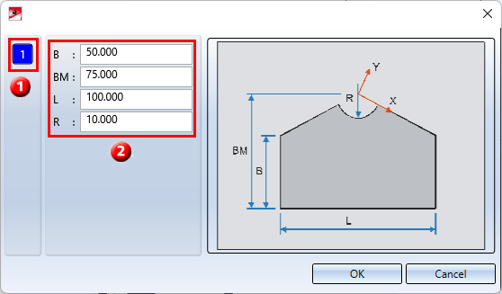
(1) Type number, (2) Corresponding parameters
To select a plate, first click the Type number (1) in the selection window. The parameters of the selected type will be displayed. You then have the following options:
- Applying the displayed parameters unchanged and clicking OK to exit the window.
- Changing the values and clicking OK to exit the window. HiCAD then asks whether you want the changed parameters to be saved. If you enter Yes, a new type is created or an existing type changed. Enter the type number. The corresponding VAD file is then changed accordingly. When you next call the window, this type number will then also be available for selection.
If you enter No, the changes will be used when fitting the plate, but the VAD file will not be changed.
After exiting the window, the dialogue window for semi-finished products selection will be displayed. Select the desired semi-finished products and exit the window with OK.
To insert the plate, HiCAD initially displays a graphic preview and asks you to specify a fitting point on the plate – e.g. the centre of the radius for the collar plate. You then specify the position of this point in the drawing.
![]() Please note:
Please note:
You can also use the Variant Editor to extend the range of VAD files. To start the Variant Editor, open the Drawing tab and select Others > Extras > Variant Editor. Alternatively, you can activate the
Variant Editor in the HiCAD EXE directory by activating the VariantenEditor.exe file.
For further information, please refer to the Online Help of the Variant Editor.
