Glass Insertion
Steel Engineering > Plate, new > Laminated glass 
Use this function derive single or double glazings from sketches in your model drawing or insert them into glass fields.
When you call the function, the Laminated glass window will be displayed.
Here you can use one of the configurations supplied by the ISD or define your own configuration.
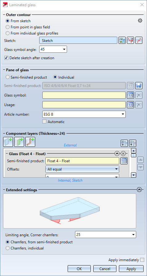
Outer contour
In this area of the dialogue window, you can select the contour that you want to use for the creation of the glass pane. You can choose between the options From sketch and From glass profiles / point in glass field.
From sketch
If you choose this option, a sketch will be used for defining the shape of the glass pane. Select the sketch that you want to use for the creation of the glass pane. If the Delete sketch after creation checkbox is active, the sketch will be deleted immediately after creation of the glass pane. Use the buttons to call the  Process sketch function, which allows you to edit an already selected sketch, and the
  New sketch in plane function, which creates a new sketch for use with this function.
From individual glass profiles / From point in glass field
If you choose these options, you can install glass in a frame. To do this, there must be a closed frame of series beams/profiles with glass points. Then select one of the profiles for the From individual glass profiles option or click in the glass field for From point in glass field. The beams/profiles surrounding this field are then automatically recognised and selected.
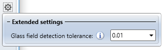
For the option From point in glass field, you can click on the  symbol to open the Extended settings docking window, in which you can determine the Glass field detection tolerance. Increase this value, e.g. to 0.1, if the detection of the glass field fails because of too large distances.
To change the orientation of the created glass symbol, you can enter a rotation angle for it in the Glass symbol angle input field. The default value is 0, i.e. no rotation, which means that the glass symbol is oriented to the coordinate system of the sketch in the case of sketch-based glasses. In the drawing, the directions "Top", "Right", "Bottom" and "Left" are shown at the edges of the glass pane, indicating the resulting orientation of the glass pane and can be changed by the value in the Glass symbol angle input field.
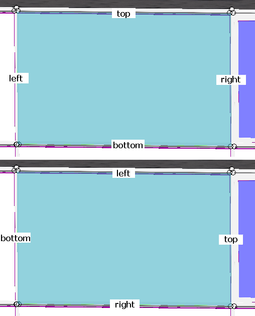
Example of Glass symbol angle: top 0°, bottom 90°.
Pane of glass
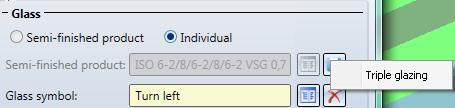
Here you can define some general settings for glass pane creation. First you can choose whether you want to configure the created glass pane according to a Semi-finished product or Individual. If you choose the settings Semi-finished product here, the same-named selection field will be activated, where you can click on the  button and select a semi-finished product from the catalogue. Otherwise this field will be greyed out. You can save the current settings as a semi-finished product to the catalogue by clicking on the
  symbol.
In the selection fields below you can select the Glass symbol and the Usage for the glass pane to be created. Use the buttons to choose a glass symbol/a usage from the catalogue or to delete  your selection again if you do not want to a glass symbol/ a usage.
The Article number entry defines the article number of the generated laminated glass. If a semi-finished product is used, the article number is defined by the semi-finished product and cannot be changed. In case of an individual layer structure, you can assign any article number here. Alternatively, you can activate the option Automatic. In this case, the part number is generated automatically by combining the designations of the individual layers separated by a separator. The default separator is "/". However, you can change this in the Configuration Editor at Steel Engineering > Products > Laminated glass pane > Separator for auto-generated article number of a laminated glass pane.
Component layers
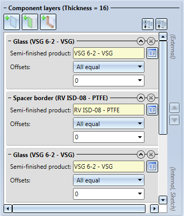
In this area you determine of which layers the glass pane is to be composed. If Semi-finished product has been selected beneath Pane of glass, you cannot specify any settings in this area. Otherwise, you can configure the layers of the glass pane here.
In the caption of this area the Thickness of the resulting glass is displayed. When inserting a pane in a glass field or glass profiles, a Target thickness will be displayed. The laminated glass can then only be created if the Thickness correlates with the Target thickness.
You can add further layers via the  Add layer with glass,
  Add interlayer and
  Add layer with distance frame buttons. The chosen layers will be added at the end of the list. You can also move the layers by marking them with a mouse click and then clicking on the
 icons to move the layers up or down in the dialogue. The uppermost layer in the list will lie directly on the sketch and the following layers below it.
The entries for the layers in the list can be expanded or collapsed with the arrow symbols 
 at the top right. In expanded state the settings for this layer are visible; the collapsed state saves space and provides a clearer overview of the layers. Click the
  button to delete a layer. When you select an entry in the dialogue, the corresponding layer is highlighted in colour in the drawing.
In the settings for a layer you can choose a Semi-finished product from the catalogue. Depending on the layer type, selection options may be very limited: If you click on the Add interlayer button you can, of course, only select interlayers. Furthermore, you have the option to define Offsets, i.e. a distance to the XY-plane of the sketch. You can choose between the options None, All equal on all borders of the layer, and Individual for different offsets for the borders of the layer. Positive offset create an offset "into" the sketch, i.e. the layer will be smaller than the sketch; negative values create an offset beyond the sketch borders, i.e. the layer will be larger than the sketch.
In the Individual mode, the borders of the sketch will be numbered. When one of the input fields has been selected, the corresponding border of the sketch will be highlighted:
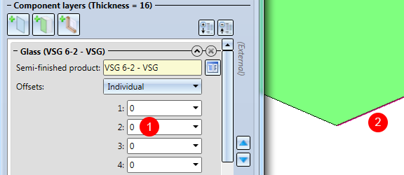
(1) Selected input field; (2) Highlighted sketch border
If you have activated the Chamfers, individual option in the Extended settings, additional input fields will appear for the glass layer entries:
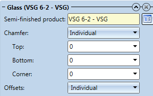
Here, too, you can choose between None, All equal if all chamfers are to have the same length, or Individual if you want to specify the chamfer lengths separately for top side, bottom side and corners.
Extended settings
Click the symbol to expand the Extended settings area:
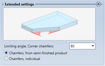
Here you can define via the Limiting angle, corner chamfers from what angle a corner chamfer is to be created for a glass pane. Angles that are smaller than the value specified here, will not be chamfered at their corners.
![]() Please note:
Please note:
- If the sketch belongs to an assembly, the glass will also be assigned to this assembly.

Save glass as semi-finished product
After defining an individual configuration for a glass pane you can save it as a semi-finished product to the catalogue and, if required, reuse it later.
To save a glass as a semi-finished product, first make sure that you have entered a correct Article number for this glass pane, since the semi-finished product will be saved to the catalogue with this number.
Then, click on the symbol next to the Semi-finished product input field.
HiCAD will then ask you to choose a table to which the new catalogue entry is to be saved. Please note that one table has always a fixed number of layers, i.e. it is not possible to store one single layer glass with 1 layer and a double glazing with 3 layers in the same table. Therefore, HiCAD will only offer tables with a matching number of layers:
If yo table exists yet for the required number of layers, HiCAD allows you to directly create a new table:
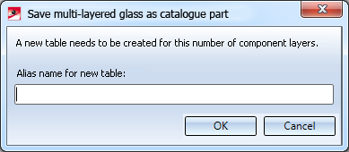
Enter a name for the new table. The table will be created and directly be selected as target table.
If an entry with the same name already exists in the selected table, you cannot save the glass as a semi-finished product here. In such cases HiCAD will display the following message:
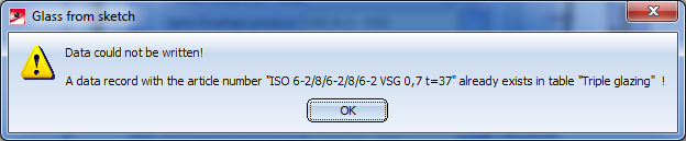
In such cases you need to change the article number and repeat the saving.
The entries will be saved to the catalogue Factory standard > Multi-layered glass panes > Semi-finished products.
