
Settings in the Configuration Editor
If the dimensions of assemblies and parts should be calculated automatically and assigned to the attributes
- Length ($03),
- Width ($02) and
- Height ($04)
of the part / assembly, this must be set in the Configuration Editor.
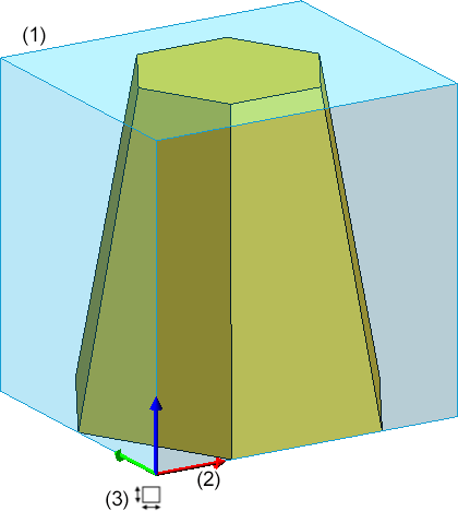
In addition, you can specify whether the dimensions should also be shown in the drawing. The display is in the form of the so-called bounding box (1). This is the smallest cuboid that completely encloses the part. In addition, the coordinate system (2) is displayed on the bounding box. The coloured arrows of the coordinate system indicate the direction of the dimensions:
- Red: x-axis (length),
- Green: y-axis (width),
- Blue: z-axis (height).
Additionally, the bounding box is marked by a symbol (3) that indicates the actuality of the dimensions as well as the source of the alignment.
Please note:
The automatic calculation of dimensions overrides manually set values of the attributes without confirmation!
Activate calculation of dimensions
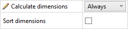
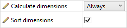
You can define whether and when the assembly dimensions should be calculated in the case of part changes in the Configuration Editor under Modelling > Part properties > Calculate dimensions.
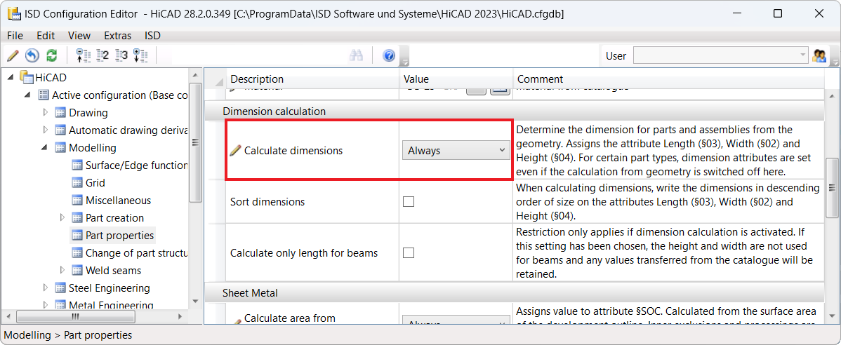
The following settings are possible there:
- Do not auto-calculate
The attributes of the module are not updated. This is the ISD default setting. - Only for automatic itemization
The attributes are updated only during the itemisation. - Always
The attributes Length, Widthand Height are updated immediately, i.e. adjusted after each change of a part or after adding more parts.
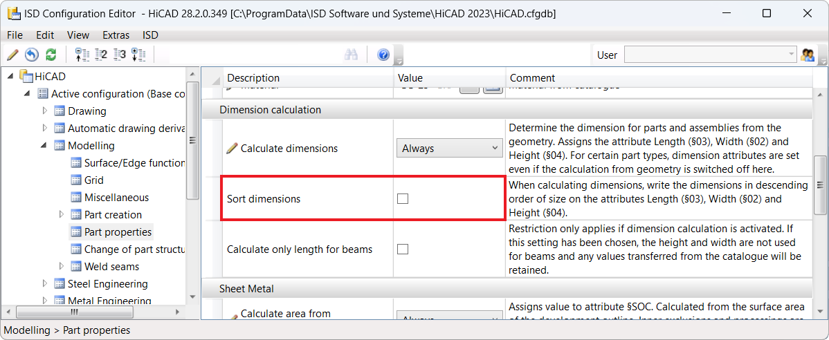
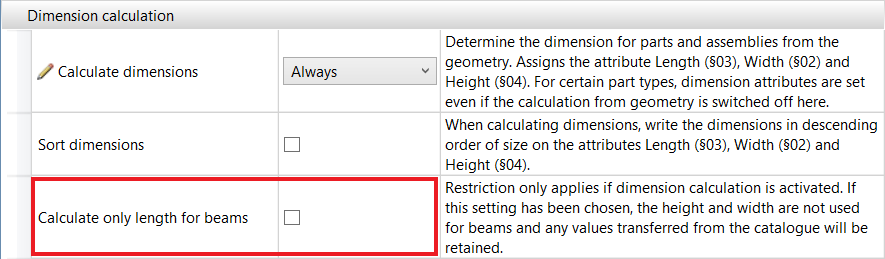
Sort dimensions
By activating this checkbox, the dimensions can be assigned to the attributes Length, Width, Height sorted by size. This means that the largest value is assigned to the length, the smallest to the height. By default, the checkbox is inactive. Switching on the sorting will only take effect after HiCAD has been restarted.
Calculate only length for beams
If the automatic calculation of dimensions is active in the Configuration Editor, the Calculate only length for beams checkbox can be used to restrict the dimension (see Special features for beams and Steel Engineering plates).
If the dimensions are to be displayed as bounding boxes in the drawing, you can specify this under System settings > Visualisation with the parameter Plot dimensions of the active 3-D part.
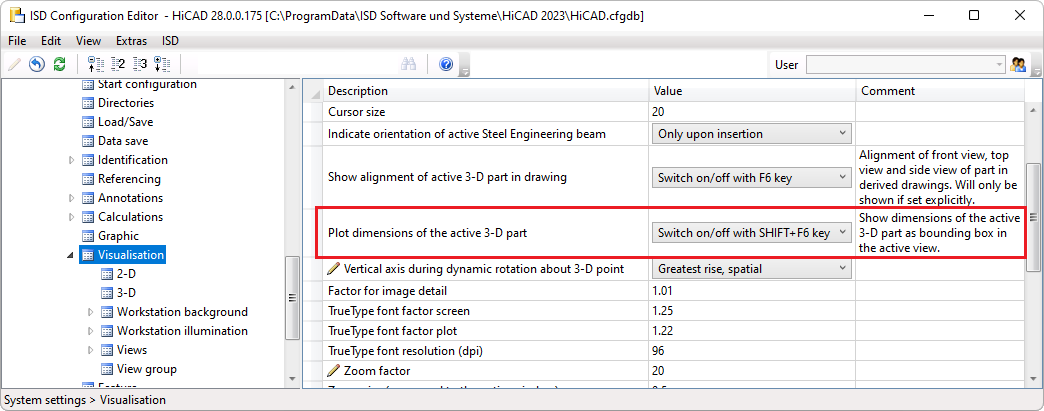
he following settings are possible:
- Never
Dimensions are not shown. - Always
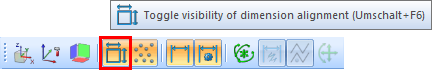
The dimensions are always shown as bounding boxes with marking of the dimension alignment. - Switch on/off with SHIFT+F6 key
The dimension display can be shown/hidden using the key combination UMSCH+F6 (SHIFT+F6). This is the ISD default setting. If this setting is active, the dimension display can also be switched on/pff via the Visibility toolbar at the bottom of the HiCAD interface. Otherwise, the symbol is locked.
![]() Please note:
Please note:
- Changes to the settings will not take effect until HiCAD is restarted.
-
The dimension is not shown in sectional and detail views, in views with cut-outs and in exploded views.
-
For parts and assemblies for which the dimensions were calculated automatically in older versions (before HiCAD 2023), the dimension will not be visualised graphically. This concerns steel engineering parts and assemblies. If the dimension is invalid and it is therefore recalculated, visualisation will take place.
-
The length of a curved Steel Engineering beam results from the length of the curved beam axis. The dimension of curved beams is not represented as a bounding box in the drawing.
Calculation of dimensions
The calculation of dimensions considers all solid parts - including those not relevant to the BOM - with the exception of the parts and geometric elements listed in the following table.
|
|
Excluded from the calculation of dimensions |
|---|---|
|
Parts / Assemblies |
The above-mentioned parts / assemblies are considered in the calculation of dimensions of superordinate parts / assemblies. |
|
Geometrical elements |
These elements are generally not considered. |
|
Parts in assemblies |
These parts are not considered when calculating the dimensions of assemblies. |
|
Curved beams |
The length of a curved Steel Engineering beam results from the length of the curved beam axis. The dimension of curved beams is not represented as a bounding box in the drawing. |
| Gratings DIN 24537 |
The bearing bar direction of gratings is always assigned to the Length ($03) attribute. The bearing bar orientation is ignored in the calculation of dimensions if the direction is set manually for the grating. This concerns the following cases:
|
The calculated values are also transferred to HELiOS if a corresponding assignment of HiCAD and HELiOS attributes has been defined with the HELiOS PDM > Others > Link > Article master sync when saving function and if the Transfer part attributes to HELiOS checkbox is active under System settings > HELiOS in the Configuration Editor.
When calculating the dimensions, the alignment of the bounding box (dimension alignment) plays an important role. It can either be set manually or it results from the part orientation, the processing direction or the part coordinate system. Detailed information on the dimension alignment and examples can be found here.
Special features for sheet metal parts
If the calculation of dimensions is active and either the setting Development attributes and Dimension attributes or Development attributes and Height is selected in the Configuration Editor under Modelling > Part properties for the Transfer development dimensions to parameter, then the calculation of dimensions for sheet metal parts will automatically be active!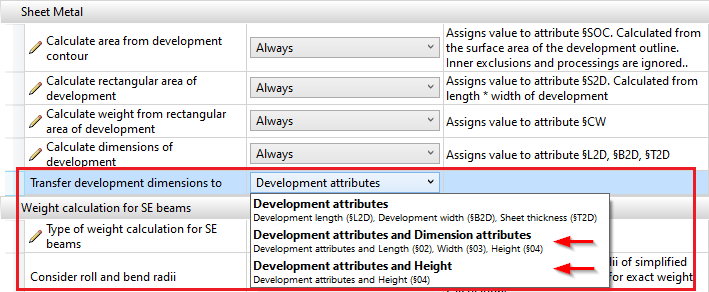
Special features for beams and Steel Engineering plates
Beams
If the automatic calculation of dimensions is active in the Configuration Editor, then the dimension calculation can be restricted via the checkbox Calculate only length for beams. If the checkbox is active, only the length is determined by the automatic calculation of dimensions when it comes to beams. This means that any values for width and height from the catalogue are retained.
By default, the checkbox is inactive.
Steel Engineering plates
If the automatic calculation of dimensions is activated in the Configuration Editor, then length, height and width are calculated and assigned to the attributes Length ($03), Width ($02) and Height ($04).
If the automatic calculation of dimensions is deactivated, then length, height and width are assigned by the Steel Engineering functions. Length and width are sorted. This means that the largest value is assigned to the length.
Examples
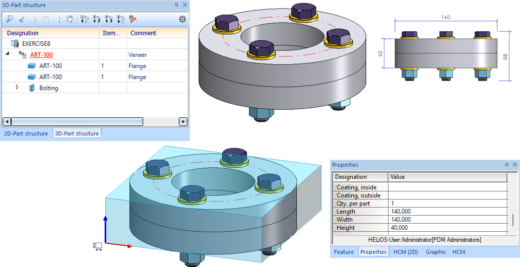
Example 1 - Bolted flanges
The figure shows an assembly consisting of two flanges bolted together. Site assembly was selected for the boltings. The boltings are not considered in active calculations for dimensioning.
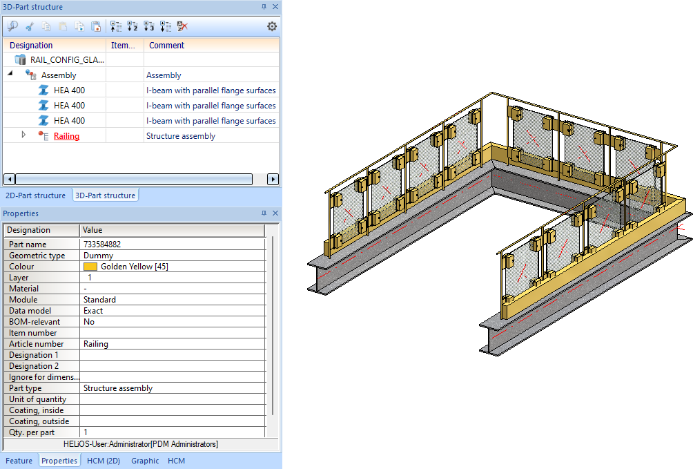
Example 2 - Drawing with structure assembly
The figure illustration shows a drawing with an assembly to which a structural assembly is subordinate. Calculation of dimensions is active.
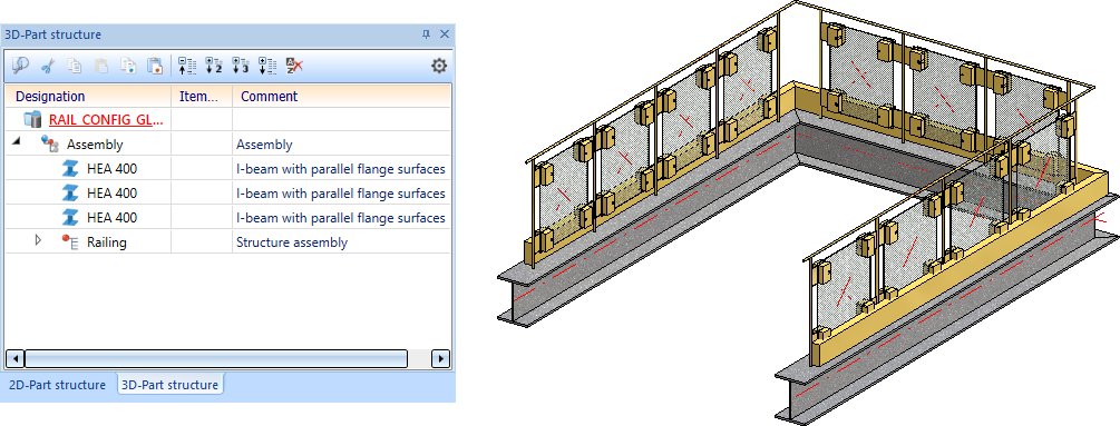
If the structural assembly Railings is selected, no calculation of dimensions will be performed.
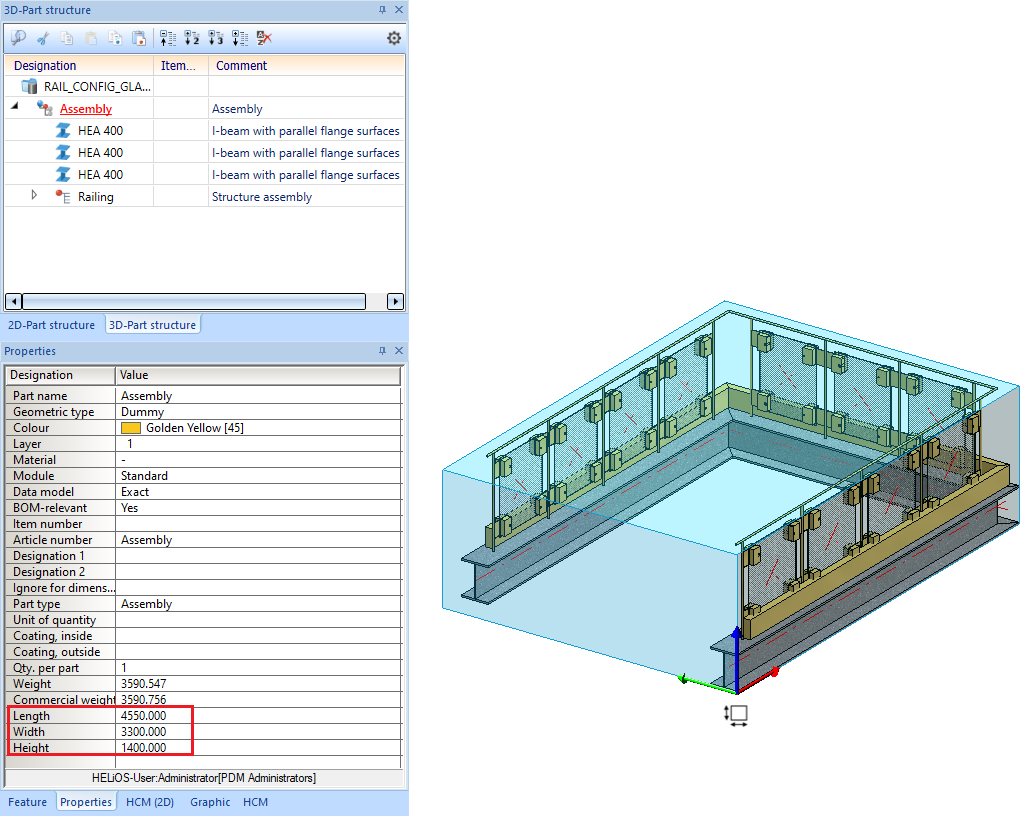
If, on the other hand, the superordinate assembly is selected, the dimensions of this assembly will be calculated taking the structural assembly into account.
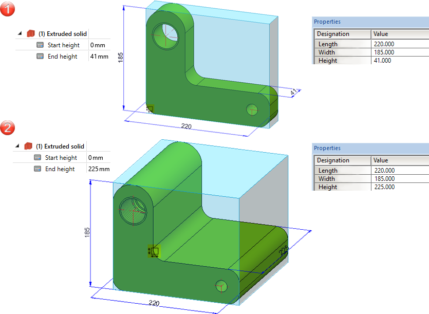
Example 3: Calculation of dimensions with / without sorting
Case 1:
In the following example, the automatic calculation of dimensions is active, but the sorting is inactive. (1) shows the initial situation. Now the height of the extruded solid is changed in the Feature (2). This changes only the Height attribute.
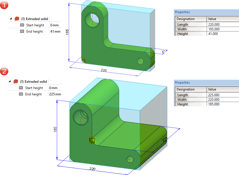
Case 2:
We consider the same example, but now both the automatic calculation of dimensions and the sorting are active. (1) shows the initial situation. Now the height of the extruded solid is changed in the Feature (2). This makes the height the largest value and assigns it to the Length attribute. The length value from step 1 becomes the width, the width value becomes the height. This means that all attribute values change.
Examples for the dimensional alignment can be found here.

Information + Communication Navigator (ICN) • Parts and Assemblies Not Relevant for Dimensioning • Dimension Alignment of Assemblies and Parts